 TIGERFASTENERS
Specifying a screw: the order the decisions happen in
You need to pick a screw and you do not know what to decide first. Here is an order: what it goes into → thread → head → drive → finish → paperwork.
Why does the order matter? Because each decision cuts off options further down. Starting in the middle usually means going all the way back, not nudging something.
But this is a suggested order, not a rule. Real projects loop back, and any of these can already be decided for you — by the product spec, by the machines the line already owns, or by a regulation. When that happens it is a constraint to work around, not a choice to make.
Most people start with the head, because it is the part you can see. It is actually third.
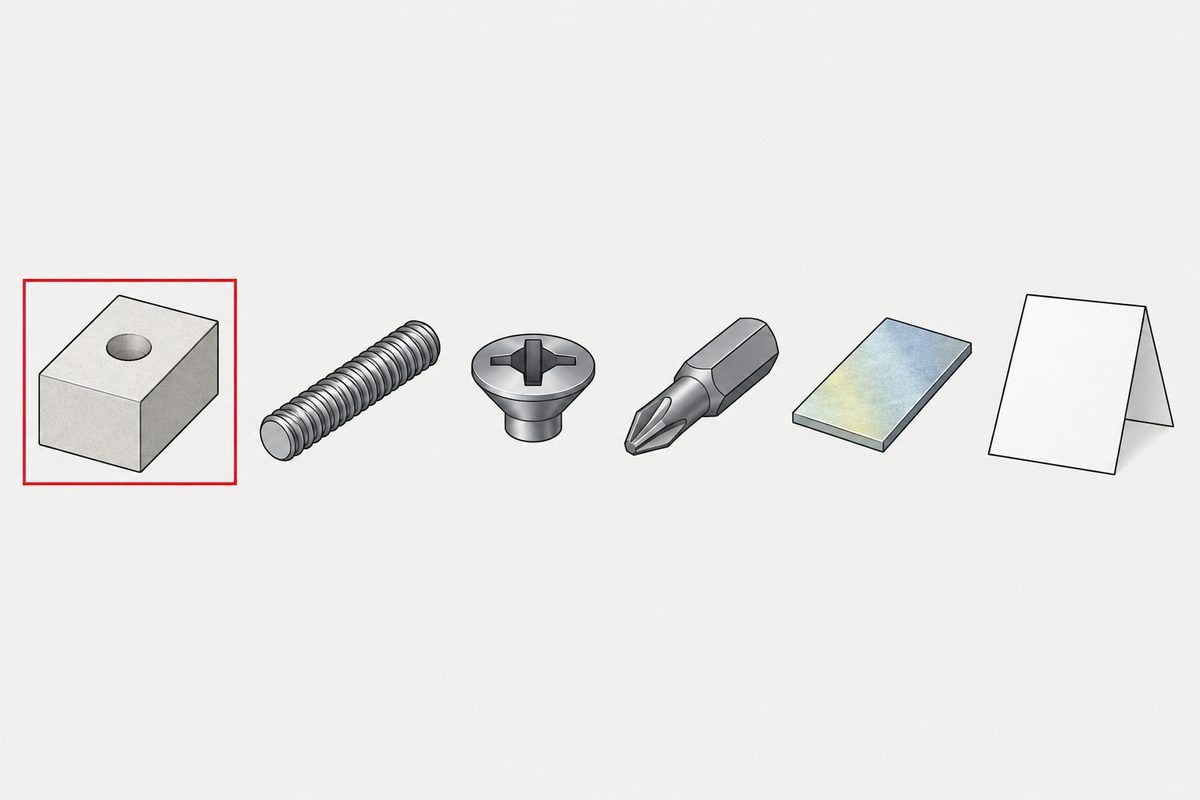
Why the order matters
A screw is not six separate choices. It is one joint, and the choices mostly push in the same direction:
One question sits before all six: what are the threads buying here. A joint that is never opened and has no preload figure on the drawing is paying for both things a threaded joint is good at and using neither, and the rest of this order assumes that has been answered.
- What it goes into → decides what kind of thread is even possible (does the screw cut its own, or match one that exists?)
- The thread → sets one of the limits on how much load the joint can take
- The head → decides how wide an area that load presses on
- How tall the head is → limits how deep the drive recess can be cut
- Hardness, which comes from material and heat treatment → limits which finishes are safe
So if you start in the middle, the things you have not decided yet come back and overturn what you just chose.
Two exceptions come up often enough to state up front.
- Corrosion requirements usually exist from day one. How long it has to survive is normally written into the product spec or a regulation. What step 5 actually decides is which coating, how thick, and by what process — not whether corrosion matters.
- The drive can be fixed before you get there too. The drivers the line already has, a customer who specifies Torx, or a security requirement — any of these works backwards and rules out some head styles.
Whatever is already decided, treat it as a constraint to design around. And expect to loop back at least once; that is normal.
One thing the order assumes throughout: the screw is clamping, not positioning. An ordinary screw in a clearance hole cannot locate anything, and where the holes go is decided by what the parent material will do, not by the screw.
And one failure that belongs to the material rather than the design: why stainless galls, which is a mechanical property rather than a chemical one.
1. The substrate — because it decides what a thread is
Why first: in different materials the female thread comes into existence in completely different ways, and those are different products rather than different options. Sometimes the answer is that the parent cannot hold a thread at all, and then the thread moves into an insert — which raises capacity and moves the failure to a new interface.
- Into plastic — the screw forms its own thread and the boss wall carries hoop stress. Screws designed specifically for direct assembly into thermoplastics often use a narrower or asymmetric thread form for this reason, though plenty of plastic parts instead take a standard 60° thread through a moulded-in or heat-staked insert. Either way clamp load falls over time through stress relaxation while the part looks unchanged. See screws into plastic.
- Into sheet or castings — the screw cuts or forms. Which one changes the chips, the torque window and the hole prep. See start with the material.
- Into an existing tapped hole or a nut — the thread already exists and the screw only has to match its class. See machine screw or bolt.
What goes wrong if you skip it: every downstream number becomes provisional. A pilot hole, a torque figure and an engagement length all mean different things depending on which of the three cases you are in.
The substrate also sets a floor. When the sheet is too thin to hold a thread covers the one that is actually in a standard — and the popular rule that is not.
And a cast substrate is not one material at all — see a die casting is not one material, where the skin disappears entirely on thick walls and porosity is often higher in it than in the core.
2. The thread — because it sets one of the load limits
Why here: diameter and pitch decide the pilot hole, the engagement length, and the torque at which a thread strips. But a joint's usable load is the lowest of several limits, not just this one — thread stripping, tension in the screw body, bearing under the head, the substrate itself, and the stiffness of what is being clamped. The thread fixes one of them, and it is the one you can settle earliest.
Length belongs here too, and it is not a leftover: the clamped length is the largest term in the bolt’s elastic resilience, so it decides how much of the preload survives embedding — and in a blind hole it decides whether the torque reading describes the joint at all.
- The pilot hole is a window, not a number — pilot hole sizing.
- Engagement length should be chosen so the screw fails before the hole does — thread engagement. Note that “one times diameter” buys fewer threads at small sizes, because pitch does not shrink as fast as diameter — micro screw sizes.
- Tolerance class is two separate decisions, width and position — thread tolerance classes.
Material and strength grade are chosen at this step, because they set hardness and hardness is what step 5 will be constrained by. They are not frozen here — step 5 can send them back, which is the loop this order expects. Changing material is a strength change, not a swap: A2-70 against 8.8.
Pitch is decided here too, and for the same reason. Fine buys about 6–9% of stress area on the screw and nothing at all on the nut side, where the pitch term cancels — so it is settled by wall depth, tapping conditions and adjustment, not by load. See why one diameter has more than one pitch.
Two questions inside this step have longer answers than they look: why the thread has one start and not two, and how the load is actually shared between the threads — which is not evenly, and not by a figure anyone can pin down.
And when the thread callout carries a tolerance class, note what it is not controlling directly: pitch has no column of its own.
Where the screw makes its own mating thread, this step also fixes the hole: thread-forming screws into metal gets about 60% of the tolerance width a tapping screw is allowed.
And if it runs the other way, say so properly: left-hand threads covers the ISO designation and what the part itself has to carry.
Where the thread meets a shoulder is its own decision: thread run-out and the undercut you have to ask for — and the standard warns the undercut may miss the loads its property class promises.
3. The head — because it decides how load enters the joint
This step has its own page — on why bearing area is the deciding variable, and what creep under an overloaded head does to preload.
Why after the thread: the head does not change where the thread strips. It determines bearing area — how load is spread into the part — and whether the surface needs preparing to receive it. It can raise usable clamp load, though, when the binding limit was bearing rather than the thread: in a soft substrate, a larger head, a flange head or a washer spreads the load and can stop the material sinking under it. So “the head cannot rescue the thread” is true of stripping, not of every failure.
- Countersunk heads make the hole part of the specification, and the angle is a pairing rather than a screw property — countersunk angles and countersunk hole dimensions.
- A washer face changes the friction interface, which changes the torque-to-clamp relationship — washers explained and SEMS screws.
The trap: head diameter cannot be reduced on its own. Shrinking it costs bearing area and limits step 4 at the same time — which is why these two steps are best checked together rather than strictly in sequence.
The head also carries geometry the hole has to clear: the fillet under the head is bounded by the product standard, and for M6 two of the three ISO 273 hole series can overlap it.
4. The drive — usually limited by the head, sometimes the other way round
Why here and not earlier: a recess is a cavity in the head, and head geometry, the section left beneath it and the forming route all press on how deep it can go — mostly settled in step 3. But this pair genuinely runs both ways. If the assembly line already has its drivers, the customer specifies Torx, automation needs low cam-out, or the part needs a security drive, then the drive is fixed first and it eliminates some head styles. Check 3 and 4 together; only the pair has to settle before step 5.
Depth of engagement is what determines whether the driver transmits torque or climbs out and rounds the recess — drive recess cam-out. At small sizes this is usually the binding constraint on assembly, not the thread.
If the drive you are handed is described only as “Y”, that is not yet a specification — two different drives are both called Y, and only one of them has a standard to point at.
And write the standard designation rather than the trademark — hexalobular is not called T20.
And if the drawing says slotted, it is worth knowing the standards are current rather than legacy: the slotted screw nobody can source.
5. The finish — known early, finalised here
Material and property class are finalised here, having been chosen at step 2. That is the one pair the order deliberately splits across two steps: the choice needs to come early because it sets hardness, and it cannot be frozen until the coating is known. They are also two separate decisions that people write as one — 8.8 encodes a nominal tensile strength and a yield ratio, while A2-70 encodes tensile strength only, so swapping between the systems changes strength and corrosion behaviour in opposite directions.
An important distinction. Whether corrosion protection matters, and to what requirement, is normally a design input you have from the start — often a regulation or a customer specification. What waits until here is which coating system, at what thickness, by what process. Two dependencies make that wait necessary:
- Dimensional. A coating adds thickness on the flanks, and the allowance for it lives in the thread tolerance you set in step 2. Below M6 a finish is a dimensional decision before it is a corrosion one — choosing a finish and plating and thread tolerance.
- Metallurgical. Acid cleaning and electroplating can introduce diffusible hydrogen. Whether that produces delayed fracture depends on hydrogen content, sustained tensile stress and microstructure as well as hardness — hardness being the property that comes from the material and any heat treatment chosen in step 2. See hydrogen embrittlement.
Also decide here what the coating is being asked to do, because salt spray hours do not predict service life, and galvanic pairing is decided by what the screw sits against rather than by the screw alone.
Anything else that ends up on the surface belongs in this step too, for the same reason: anti-seize redefines the friction condition the torque figure was written against.
6. The documentation — specified early, issued last
Why last, with the same caveat as step 5: documentation requirements — traceability, PPAP, a particular certificate type — often arrive at the beginning and constrain the design, so establish them early. What happens last is issuing the final version, once the technical decisions are frozen. Everything above is a decision someone has to verify later; if it is not written down, the next person re-decides it, usually differently.
- What the drawing has to state, including that untoleranced dimensions need a source — the title block.
- What evidence you are asking for about the material — mill test certificates. The type number carries the evidence level; the document's name does not.
- If any of the five change later, what has to be re-verified — screw change revalidation.
A drawing that calls out a countersink is also making a measurement promise: the angle cannot be measured directly, so what gets inspected is a diameter. A grade mark is part of that evidence trail, and it is worth knowing that the mark is a claim rather than a certificate.
And where the drawing carries a fit rather than a plain dimension, the letters are doing specific work: one hole, three shafts, three different joints.
A torque figure on that drawing is incomplete without the surface condition it was calibrated against: a torque figure assumes a friction condition.
Some of that documentation is not on paper at all: the class number and maker mark stamped into the head. What the markings on a bolt head mean covers what is required, and why an unmarked head usually proves nothing.
When it has already gone wrong
The order is also a rough diagnostic. A failure often traces back earlier than the step that appears to have failed — but assembly conditions cause more field failures than specification does, so check those first where noted:
| What you see | Look here first |
|---|---|
| Stripping | Step 1–2 — which member stripped tells you which stripped threads |
| Recess rounding out | Driver bit fit and wear, down-force and speed settings first; then steps 3–4, where head height limited recess depth — cam-out |
| Loosening | Rarely a specification problem. Check achieved preload and tightening control, joint embedment and stiffness, and whether external load is making the faces slip. Only then pitch and locking method — and note rotational self-loosening and preload loss are different failures |
| Rust | Step 5, then step 2 — stainless rusts three ways |
| Gauged fine before plating, tight after | Steps 2 and 5 — coating thickness against thread allowance. A part that simply will not go in is a wider symptom — check wrong item, hole position, burrs and cross-threading before assuming this |
| Broke well below its rated load | Not the class — check how load reaches it. A flexing bracket adds a prying reaction on top of the applied load, and in a group the end fasteners do not carry an equal share |
| Failed after long service, no overload | Fatigue. Note that a published fatigue limit is a test convention rather than a promise, and that tightening harder is not always the fix |
| Will not start, or cross-threads immediately | Before anything else, confirm it is the thread system you think it is — metric and inch sizes exist that a caliper cannot separate |
| Self-drilling screw stops part-way, burns or snaps | Step 1 — the stack may exceed the point's drill capacity, which is not the grip range and counts the gaps between layers |
Where the standards themselves stop applying is its own question — see where standards stop.
And the first question people actually ask when a hole has stripped: is there something you can pour in. Three of the four usual candidates are rated for something other than load.
Common questions
What order should I decide a screw's specification in?
As a default: substrate, then thread, then head, then drive, then finish, then documentation. It is a working order rather than a design law. Each step tends to constrain the next, so starting in the middle usually means going back — but real projects iterate, and any item that arrives pre-decided by the product, the assembly line or a regulation is an input to design around rather than a decision to make.
Why does the material I am screwing into come first?
Because it decides what kind of thread can exist at all. In plastic the screw forms its own thread and the boss carries hoop stress; in sheet metal it may cut or form; in a tapped hole the thread already exists and the screw only has to match it. These are different products rather than different options for the same product, so most decisions downstream stay provisional until this one is settled.
Why is the finish decided near the end rather than at the start?
It is not — the requirement usually is a design input from day one, often set by a regulation or customer specification. What waits is which coating system, thickness and process, and that waits for two reasons. A coating adds thickness to the thread flanks, and below M6 that is a significant fraction of the tolerance, so it cannot be judged until the thread is fixed. And plating can introduce diffusible hydrogen, whose risk depends on hardness among other factors, and hardness comes from the material and heat treatment chosen earlier.
Can I skip straight to a part number from a catalogue?
You can, and it usually works when the joint is unremarkable and someone has solved it before. This order is for the cases where it did not work — a screw that strips, will not drive, or corrodes. Those often trace back to a decision made before the one that appears to have failed, though loosening in particular is more often an assembly and preload problem than a specification one.
What is the most common mistake?
Deciding the head first, because it is the visible part. Head style constrains bearing area and how deep the drive recess can be, and it cannot move where a thread strips — though in a soft substrate a larger head or a washer can raise usable clamp load, because there the limit was bearing rather than the thread.
Ask us
If you are at step 1 with a part and no specification yet, send the drawing or the application and we will work through the order with you. sales@tigerfasteners.com
Request a quotation
Tell us the part and the quantity. We will come back on feasibility, lead time and price.
Or email us directly sales@tigerfasteners.com