 TIGERFASTENERS
The fillet under the head: your clearance hole may not clear it
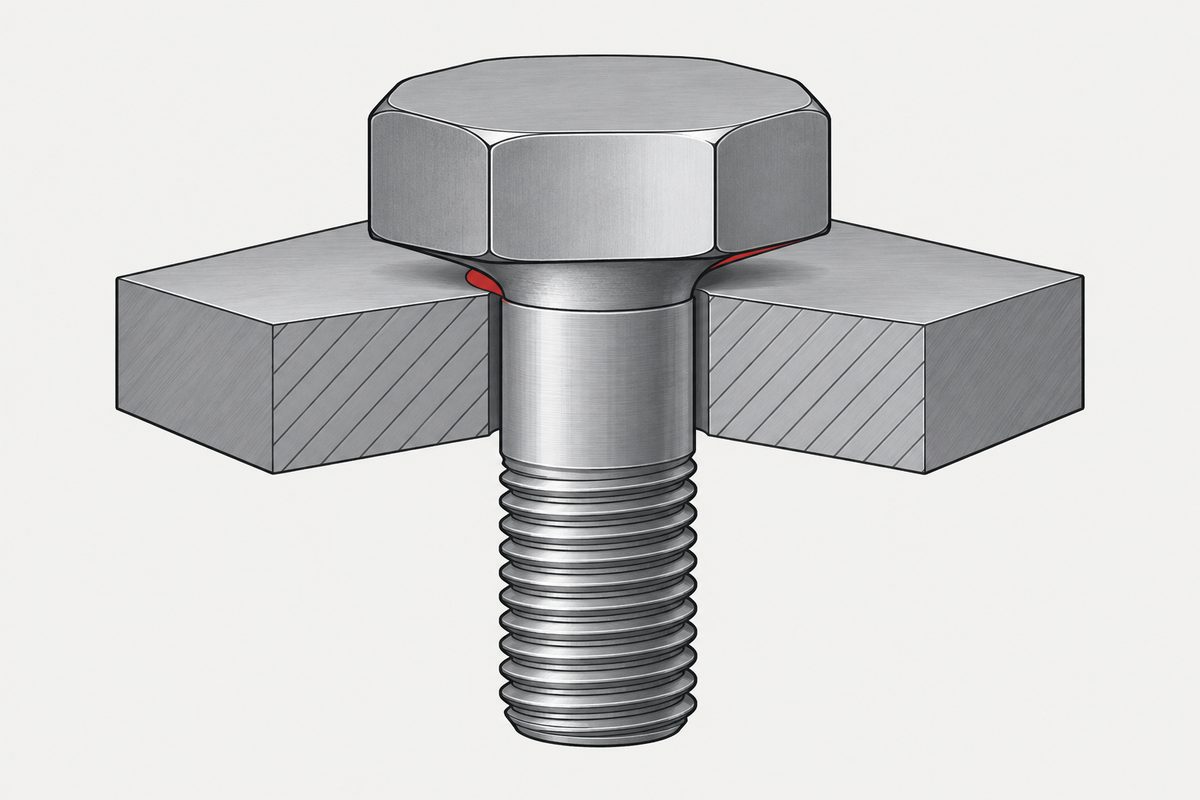
The curve where a bolt head meets the shank is controlled geometry, not what is left over from forming it. ISO product standards bound it at both ends, and ISO 273 contains a quiet note about clearance holes that most drawings never act on. Whether it matters for your joint comes down to two numbers you can look up.
What the product standards actually fix
The fillet is not left to the maker. It is bounded, and differently by head type.
| Standard | What it specifies |
|---|---|
| ISO 4762 (socket head cap screws) | rmin per size in Table 1; rmax = (da,max − ds,max) / 2; lf,max = 1.7 rmax; and da,max |
| ISO 4014 / 4017:2022 (hex head) | rmin and da,max, with permissible minimum and maximum underhead fillet shown in the figure. No general formula for rmax — the envelope is controlled by the figure and those dimensions |
da is worth naming properly, because it gets misused. ISO 225 defines it as the transition diameter — the inner diameter of the bearing face where it transitions to the underhead radius. It is not the fillet radius. What it gives you is the maximum radial envelope of the head-to-shank transition, which is exactly the number you check a hole or a washer bore against.
One thing the standards do not say: they specify the geometry, but none of them declares the purpose to be fatigue stress relief. That the fillet radius affects stress concentration at the head-shank transition comes from the mechanics literature, not from the ISO text. It is a fair statement — just not one you can cite a product standard for.
The note in ISO 273 that drawings ignore
ISO 273:1979 carries a note after its clearance hole tables: where interference between the edge of the clearance hole and the underhead radius has to be avoided, chamfering the hole is recommended.
Note the wording. It is recommended where necessary, not required for every ISO 273 hole. Which means the useful question is whether your hole and your bolt actually overlap. For M6:
| Dimension | Value | Against da,max = 6.8 mm |
|---|---|---|
| ISO 273 fine | 6.4 mm | Smaller — overlap possible |
| ISO 273 medium | 6.6 mm | Smaller — overlap possible |
| ISO 273 coarse | 7.0 mm | Larger — clears |
So for an M6 socket head or hex head screw, two of the three standard hole series can geometrically interfere with the head transition and one cannot. That is a comparison you can do for any size in a minute, and it is more useful than a rule of thumb.
“Can interfere” is not “does interfere”. These are maximum envelopes against nominal holes; the actual parts may clear. The point is that the fine and medium series are the ones where you have to look.
What interference actually costs you
NASA-STD-5020A is explicit about the consequence, and it is not the one we expected to write. Its clause on this requires clearance for the fillet where interference must be avoided, and the stated reasons are that interference can make preload unreliable, reduce strength, or give inadequate separation resistance.
In other words the first thing you lose is the bearing face doing its job. If the hole edge is carrying part of the load through the fillet, you no longer know what the bearing face is carrying, and preload becomes a number you cannot trust.
Two things we were going to write that are wrong
-
“Use an ISO 7090 chamfered washer with the chamfer toward the
head.” We had this backwards.
ISO 7090's chamfer is on the outside diameter — its scope
says so in those words, “chamfered at the outside diameter” — and
its bore is the same as ISO 7089. It cannot provide clearance for
an underhead fillet, and neither ISO 7089 nor ISO 7090 specifies an assembly
orientation at all.
The requirement that does exist is in NASA-STD-5020A: where interference must be avoided, use a chamfered hole, or a washer with a countersunk bore under the head, countersunk face toward the bolt head. That is a genuine “washer to clear the fillet” rule — but it applies to NASA threaded fastening systems, and it needs a washer that actually has a countersunk bore. A plain washer turned round does nothing. - “The fillet is where bolts break.” It is not the primary site. NASA RP-1228 states that bolts under cyclic tension usually fail near the end of the threaded portion, where the stress concentration is highest, and peer-reviewed failure work lists the first engaged thread, the thread runout and the head-to-shank fillet as the three locations — in that order.
The 65 / 20 / 15 figure, and where it comes from
You will meet a distribution: 65% at the first engaged thread under the nut face, 20% at the thread runout, 15% under the head. It is quoted constantly. It is worth knowing what it actually is.
The traceable source is B. Taylor, “The Strength of Large Bolts Subjected to Cyclic Loading”, Transactions of the Institute of Marine Engineers, Vol. 64, 1952 — and Taylor is relaying data from W. Staedel, 1933.
We could not find Staedel's original statistics, so the sample size, the equipment, the loading conditions and the inclusion criteria are all unverifiable. We also looked in VDI 2230 Blatt 1, NASA-STD-5020A and the ASM Handbook volumes on fastener failures and fatigue of mechanically fastened joints, and found no position distribution percentages in any of them.
So use it as what it is: 1933 data relayed by a 1952 paper, useful for the ranking it implies, not as a modern probability for your joint.
What we can say, and what we cannot
Supported: the fillet is controlled design geometry, bounded above and below by the product standard. Interference with the hole edge is a recognised risk that ISO 273 tells you to design around where necessary, and NASA-STD-5020A tells you the consequences are unreliable preload, reduced strength and inadequate separation resistance.
Not supported: that any contact automatically adds a notch. We wanted to end there and it goes further than the evidence. Whether contact produces local damage, and what that does to fatigue life, depends on the actual clearance, the contact geometry, material hardness and the load. The standards say interference should be avoided; they do not say contact equals a new stress raiser.
The practical version is duller and more useful: look up da,max for your size, compare it with the hole you specified, and chamfer if they overlap.
Where this connects
What the head is doing mechanically is in choosing a head type; what a washer is and is not for is in washers explained; the limits on forming a head at all are in head forming limits; and the hole side of this is in countersunk hole dimensions.
References
- ISO 4762:2004 — clause 3, Figure 1 (maximum underhead fillet), Table 1: rmin, da,max, rmax and lf,max formulae
- ISO 4014:2022 and ISO 4017:2022 — clause 4, Figure 2, dimension tables: rmin, da,max, permissible minimum and maximum underhead fillet
- ISO 225:1983 — definition of transition diameter da
- ISO 273:1979 — clause 2, note after the tables: chamfering recommended where interference with the underhead radius must be avoided
- NASA-STD-5020A — clause 4.7.3, TFSR 22: chamfered hole or countersunk washer with the countersunk face toward the bolt head; stated consequences of interference
- NASA RP-1228, Fastener Design Manual — failure near the end of the threaded portion
- Mushtaq et al., Engineering Failure Analysis 122 (2021) — first engaged thread, thread runout, head-to-shank fillet
- B. Taylor, Transactions of the Institute of Marine Engineers, Vol. 64 (1952), relaying W. Staedel (1933) — the 65 / 20 / 15 figure
Acceptance for any particular joint is governed by your drawing and the standards it invokes.
This page covers step 3, the head. The whole order is substrate, thread, head, drive, finish, documentation, and why doing it out of order is rework rather than a tweak is in specifying a screw.
Common questions
Is the radius under a bolt head controlled by the standard?
Yes, at both ends. ISO 4762 gives a minimum fillet radius per size in Table 1 and bounds the maximum through r max = (d a,max minus d s,max) divided by 2, with l f,max = 1.7 r max. ISO 4014 and ISO 4017:2022 give r min and d a,max with permissible minimum and maximum fillets shown in the figure, though without a general formula for r max. What the standards do not do is state a purpose; that the fillet radius affects stress concentration comes from the mechanics literature, not the ISO text.
What is d a on a bolt drawing?
It is the transition diameter, defined in ISO 225 as the inner diameter of the bearing face where it transitions to the underhead radius. It is not the fillet radius. Its practical use is as the maximum radial envelope of the head-to-shank transition, which is the number you compare against a clearance hole or a washer bore.
Does a clearance hole need to be chamfered?
Only where it needs to be. ISO 273:1979 notes after its tables that chamfering is recommended where interference between the hole edge and the underhead radius must be avoided — a recommendation where necessary, not a blanket requirement. The check is arithmetic: for M6 the transition envelope d a,max is 6.8 mm, while the fine and medium hole series are 6.4 and 6.6 mm, so both can overlap, and the coarse series at 7.0 mm clears.
Should a chamfered washer go chamfer-side up to clear the fillet?
Not with ISO 7090. Its scope describes it as chamfered at the outside diameter, and its bore is the same as ISO 7089, so it provides no clearance for an underhead fillet, and neither standard specifies an orientation. The rule that does exist is in NASA-STD-5020A: where interference must be avoided, use a chamfered hole or a washer with a countersunk bore under the head with the countersunk face toward the bolt head. That needs a washer that actually has a countersunk bore.
Do most bolts fail at the underhead fillet?
No. NASA RP-1228 states that bolts under cyclic tension usually fail near the end of the threaded portion, where the stress concentration is highest, and published failure work ranks the first engaged thread, the thread runout and the head-to-shank fillet in that order. The often quoted 65 / 20 / 15 split traces to a 1952 paper relaying 1933 data whose original statistics we could not verify, and no position distribution appears in VDI 2230, NASA-STD-5020A or the ASM Handbook volumes we checked.
Enquiries
If you are not sure whether your hole clears the head transition, send the bolt standard, the size and the hole you specified. It is a two-number check and we would rather do it before the parts are made.
Request a quotation
Tell us the part and the quantity. We will come back on feasibility, lead time and price.
Or email us directly sales@tigerfasteners.com