 TIGERFASTENERS
Choosing a head type: what fails under the head is not what you expect
Beginners choose a head by how it looks — which one sits flatter, which one looks right — or by which driver is already on the bench. Neither is a wrong consideration. Both are downstream ones.
The upstream question is single: what is this screw pressing into?
Because what the head actually does is push preload into the clamped parts through a finite area. Whether that area is big enough is one of the things deciding whether the joint stays tight, or quietly loses preload while every part still looks perfect.
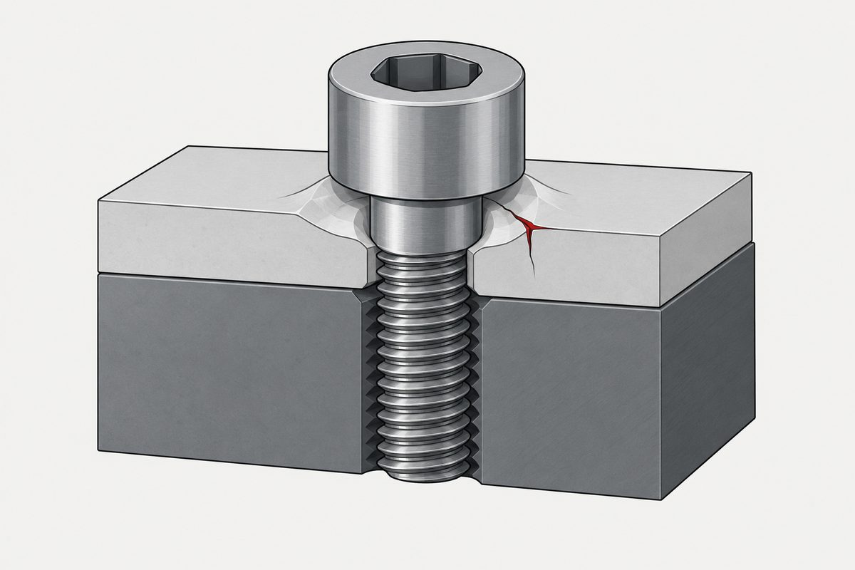
Spreading the load with a bigger head is sound thinking
Pressure is force over area, so a wider head puts the same clamp force over more material. That is correct, it is how bearing area is meant to work, and it is the right move often enough to be a habit.
It also has an obvious failure picture attached: too much pressure and the surface crushes. That picture is what makes the more common failure hard to see coming, because it does not look like crushing at all — the material beneath the head settles over time and the preload goes with it.
The head is a device for spreading pressure
Tightening a screw builds tension in the shank, and that tension has to react against something. It reacts against the ring of bearing surface under the head, which is where the load passes into the clamped material.
The force is fixed — it is the preload you wanted — so less area means more pressure. That is division, not engineering judgement. The same 2 kN under a wide flange and under a small pan head puts pressures on the material that differ several times over.
And what the material can take has a ceiling.
So use a bigger head — and what fails there is not what you expect
VDI 2230, the guideline for the systematic calculation of bolted joints, has a dedicated step for this — determining the surface pressure and comparing it against a limiting value pG for the material.
Be precise about which material. The check applies to the part the bearing face actually presses on — under the head, and separately under the nut, each against what it is in contact with. It is not a search through the stack for the softest layer. A soft layer buried inside the joint is a real problem, but a different one, analysed through the joint's relaxation rather than through bearing pressure, because it carries neither the head's contact area nor its pressure.
Exceed the limit and the intuition is crushing or a visible dent. That case exists and is the easier one, because you can see it. The one worth understanding is creep:
Above the limiting pressure the bearing material may creep, and embedding may then grow in an uncontrolled way. The standard states it as a risk rather than a certainty, and two qualifications matter.
First, timing. Embedding that happens during tightening does not reduce the preload you end up with — it is taken up as you tighten. It is plastic deformation after assembly that costs you.
Second, it is not a one-for-one trade. How much preload a given amount of settling costs depends on the compliance of the screw and of the clamped parts — VDI 2230 expresses the loss as embedding divided by the sum of those compliances. A stiff screw through thin, stiff parts loses far more preload per micrometre of settling than a long screw through a compliant stack.
Where it does happen the symptom is unhelpful: the joint loses preload while the screw is unbroken and the threads are undamaged, so the parts can still pass inspection and the cause is hard to attribute.
Which connects to why screws loosen — bearing pressure is one of the routes, and the quietest of them.
The bearing area is smaller than you think
An easily missed detail: the hole chamfer has to be deducted when working out bearing area. VDI 2230 requires the allowance explicitly.
Holes are usually chamfered — deburring, easier location — and the head cannot bear on what has been chamfered away. So the effective area is the annulus between the head's outside diameter and the chamfered hole diameter, not the full circle the head diameter suggests.
On small screws this bites hardest. An M3 head is a few millimetres across; a 0.3 mm chamfer removes a meaningful fraction of it. And drawings usually do not state the chamfer size.
Countersunk heads are a different mechanism: wedging, not pressing
Everything above assumed a flat face under the head. A countersunk head does not have one.
It contacts the cone of the hole, so it does not press on a face — it wedges into a tapered seat. That gives it two properties:
- It tends to self-centre — provided the two cones are coaxial and matched in angle, there is clearance left to move, and friction has not already locked it. Under those conditions the cone pulls the screw toward the hole's centre, which also means a mislocated hole will drag the part across.
- It converts part of the axial load into a radial outward force. Ignoring friction, a cone of half-angle α gives a radial-to-axial ratio of cot α — so for a 90° countersink, where α is 45°, the two are of the same order. Distributed around the circumference that radial push raises hoop tensile stress, which is what splits a brittle part, a thin section or a hole close to an edge.
It is also unusually sensitive to angle: the screw's included angle and the hole's must match. When they do not, contact concentrates in a narrow band — which is the extreme version of "the bearing area got smaller". That has its own page, and how to dimension the hole has another.
So the order runs like this
A default working order, not a complete decision procedure and not one-way. Real designs iterate, and several constraints not listed here can override any step: head strength, installation clearance and tool access, the friction that sets the torque-to-preload relationship, washer thickness and hardness, sealing, fatigue and edge distance. Where flushness is fixed by the product it is an input rather than a choice, and it arrives before step one.
- What the bearing face presses on — the part directly under the head, and under the nut if there is one. Steel, aluminium, zinc alloy and plastic tolerate very different pressures. Plastic tolerates least, and changes with temperature.
- How much preload is needed. That sets the force being pushed through — see torque and clamp force.
- Therefore how much bearing area. Force divided by what the material can take. For metals the limiting values live in VDI 2230's Table A9; this page deliberately does not reproduce a number, since they are per-material room-temperature short-term reference values and a figure lifted out of that context gets misapplied. For plastics that table is not the source at all — it does not cover general plastics, and you need compression and creep data for the specific resin at your temperature, moisture content and load duration, usually backed by a joint test.
- Pick a head that provides that area, or make it up with a washer. A flanged head is loosely a washer integrated into the part — one fewer component, one fewer chance to omit it — but treat that as an analogy rather than an equivalence, since the two differ in friction interface, in whether anything can rotate against the surface, and in effective spread diameter, stiffness, hardness and finish.
- Does the surface need to be flush — if so, countersunk, accepting the wedging cost and the angle requirement above.
- Only then drive type and appearance. They matter. They should not decide the five above.
Driving into plastic is the case that goes wrong most, and not only because it needs more area — plastic has a low limiting pressure, creeps, and shifts with temperature and moisture. That has its own page.
A note on scope. VDI 2230 addresses high-duty bolted joints, typically metal to metal with a defined preload requirement. What this page borrows is its concept — check bearing pressure against the limit for the material in contact — not a claim that it applies directly to a tapping screw in plastic. The concept transfers; the calculation method does not transfer wholesale.
Whichever head you pick, check the transition diameter against your clearance hole: the fillet under the head.
What the drawing should say
- Head name and standard number. "Pan head" is not a specification; "ISO 7045 cross recessed pan head" is.
- Tolerance on head diameter and head height. Height drives clearance; diameter is the bearing area.
- The hole chamfer. If you calculated a bearing area, dimension the chamfer too, or the area you calculated does not exist.
- For countersunk, the hole's included angle, matching the screw.
- If a washer is making up the area, put it on the BOM and mark it as not optional. It looks like a discretionary part and is actually part of the bearing area.
This page is step three of the order in which a screw gets specified. Material and thread come before it; finish and documents come after.
Common questions
How should I choose a head type?
Start from what the screw presses into, not from appearance or the driver you own. The variables are bearing area and the pressure the material tolerates: softer material needs more area.
What happens if pressure under the head is too high?
Often not crushing but creep. Above the limiting pressure the material may creep and embedding may grow; what costs preload is deformation after assembly, and how much it costs depends on the compliance of the screw and the clamped parts. Where it happens, the joint loses preload while the parts can still pass inspection.
Does a countersunk head have less bearing area?
It has no flat bearing surface at all — it wedges into a cone. That buys self-centring and flushness, at the cost of an outward force component and real sensitivity to matching angles.
Can a washer replace changing the head?
Yes; a washer's job is to enlarge bearing area. The cost is an extra part and an extra chance to omit it, which is why production tends to move to a flanged head.
What should the drawing say?
Head name and standard, tolerances on head diameter and height, the hole chamfer, and for countersunk the hole angle. "M4 pan head cross recess" alone leaves the bearing area to be guessed.
Related
- The order in which to specify a screw — this page is step three
- Torque and clamp force — where the force being pressed through comes from
- Why screws loosen — bearing pressure is the quietest route
- Screws into plastic — the lowest limiting pressure, and the easiest to exceed
- Countersunk angles — what mismatched cones do
- Countersunk hole dimensions — how to dimension the seat
- What washers are for — the part that enlarges bearing area
- Head forming limits — why some heads cannot be made
Enquiries
Tell us what the head will be bearing on and how much clamp force you need, and we will come back on which head types give enough bearing area and which need a flange or a washer to get there. Head tooling below M6 is in house, so whether the head can be formed at all is part of the same answer.
Request a quotation
Tell us the part and the quantity. We will come back on feasibility, lead time and price.
Or email us directly sales@tigerfasteners.com