 TIGERFASTENERS
Countersunk angles: 82°, 90°, and the hole
The short version: a countersunk angle is a pairing, not a screw specification. Get the two angles wrong against each other and the head either stands proud or drops onto the small end, and the cone that was supposed to seat becomes a single circle of contact. 82° and 90° belong to two different systems — though the inch standard is not a single-angle standard either: ASME B18.6.3 carries 100° machine screws of its own alongside the 82° ones, so the thread system never determined the angle. Cabinet work has pushed demand out to 100°, 110° and 120° — while heads keep getting thinner and smaller at the same time. The three move together.
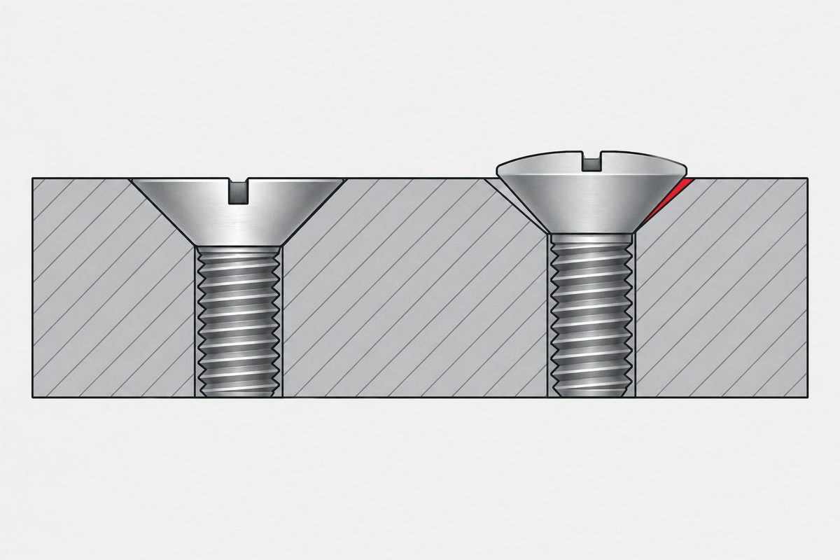
It looks like a choice, and it is drawn like one
Every countersunk screw catalogue lists both 82° and 90°. They sit next to each other like two finishes or two head sizes, so treating the angle as a preference is exactly what the presentation invites.
And most of the time nothing goes wrong, because a whole assembly usually comes from one standard and the angles match without anybody thinking about it. The problem only shows up when a drawing quotes one standard and the screw comes from another.
So pick 90° — except it was never yours to pick
The common misunderstanding is treating the angle as a preference. It follows the standard the drawing cites:

| Angle | Source | Typically seen in |
|---|---|---|
| 82° | ASME B18.6.3 inch series flat head machine screws | Inch drawings, North American supply chains |
| 90° | ISO 7046 (cross recess), ISO 10642 (hex socket) and others | Metric drawings; most items in our size range |
| 100° | Common in aerospace series | Flush joints in thin sheet needing more bearing area |
| 110° / 120° | Usually made to drawing, not to a standard | Cabinet and thin-sheet work (below) |
So “M3 countersunk” has not finished describing the part. Until the angle and its standard are stated, both 82° and 90° satisfy the words — and they do not do the same thing in the same hole.
What a few degrees actually does
Treat the head and the countersink as two coaxial cones. Once the included angles differ, they can only meet on one circle. Which circle depends on whose cone is steeper:
- Screw angle smaller than hole angle (an 82° screw in a 90° hole): the head cone is steeper than the hole, so contact lands on the top rim and the head stands proud. Flush is not available.
- Screw angle larger than hole angle (a 90° screw in an 82° hole): the head cone is flatter, so contact drops to the small end at the bottom of the countersink, loading the thinnest part of the hole.
Wherever it lands, the consequences are the same set:
- Face contact becomes line contact. Local stress rises; thin sheet can dish, or the edge of the hole rolls over
- The head face is not parallel to the surface, so “flush” is only flush to the eye
- The friction radius changes, and with it the torque-to-clamp relationship. If the joint is torque controlled, those parameters were established on a correct pairing — the same argument appears in the stack-up article, and it does not survive a changed pairing.
This one hides from inspection. The screw measures good. The hole measures good. Two conforming reports, and the joint still will not sit flat — because nobody measured this screw in this hole. And measuring the hole is its own problem — almost nobody measures the angle itself.
And there is a second mechanism, which does not need anybody to have made a mistake at all. The hole and the head are tolerated in different documents, and their ranges are not centred on each other:
| Feature | Source | Included angle |
|---|---|---|
| The hole | ISO 15065:2005 §3, Figure 1 | 90° ±1° → 89° to 91° |
| The head | ISO 10642 published dimensional data | 90° to 92° |
A conforming 89° hole and a conforming 92° head are three degrees apart. Both pass their own inspection. Nobody mixed standards, nobody quoted the wrong chart — the ranges simply overlap without being centred on each other, which is what happens when two features made by different processes in different factories are tolerated independently and then asked to mate. ISO 10642:2026 says so itself, warning that alignment of the head and countersink bearing surface needs particular attention.
So “matched angles” is a nominal statement, not a guarantee about the two cones you actually have in front of you.
Which is why the angle stays in every permitted callout format, in both standards systems: two callout systems. And if the drawing is going to a Taiwanese supplier, note that the head has four names in Chinese and the standards use a different one from the trade.
Where 100°, 110° and 120° come from
It is a geometric trade, not vendors inventing variants. Opening the included angle buys a larger head diameter for the same head height, and a shallower countersink. When thin sheet has to keep bearing area while the head gets flatter, that is the direction with something to give.
Cabinet work is where we have actually seen demand move that way: thin panels, flush required, and a head that must not be small enough to pull through. That is what has come across our own desk — not a classification from a standard. 82° and 90° have standards behind them, 100° is common in aerospace series, and beyond that you are generally working to a drawing.
Thinner and smaller heads leave less to work with
The other half of the demand is the head itself. Three things move together:
- Bearing area falls. The same clamp load presses on a smaller annulus, so pull-through risk in thin sheet rises
- The countersink can break through the sheet. If head height exceeds sheet thickness the countersink cuts through and leaves a knife edge — which neither survives handling nor provides a bearing face
- Recess depth gets squeezed. A thinner head cannot carry a deep cross recess or hex socket, so driver engagement is shallower and cam-out becomes more likely
Head diameter is therefore not a dimension you can shrink on its own. It moves bearing area, countersink depth and drive engagement at once — and at small sizes there is a separate limit on whether the head can be formed at all.
Flushness and angle are two requirements, not one
Most arguments about a countersink are really two requirements wearing one name. Installation specifications tend to control the installed height. Hole standards control the geometry. Neither one implies the other.
NASA PRC-9007C §3.0 is the clearest example of the first: it requires countersink diameter and depth to be specified such that installed fasteners meet a standard maximum protrusion of 0.010 in, unless the drawing gives an alternate tolerance. That is a statement about where the top of the head ends up — not about the cone.
ISO 15065 still normatively controls angle, diameters and coaxiality. So both of these are real, and they bite in opposite directions:
- A hole can fail its specification while the screw you happened to fit sits perfectly flush
- A conforming hole with a screw at the opposite dimensional limit can give a different installed height
Flush appearance is not proof of adequate bearing contact, of concentricity, or of a compliant hole. It is proof that one screw ended up level in one hole.
The reverse case — angle within tolerance and the head still standing proud — has plenty of ordinary mechanisms, and none of them is an angle problem:
- Countersink major diameter undersized, or insufficient axial depth
- Screw head at its maximum actual diameter, or head height at its limit
- The head-to-shank fillet fouling the pilot hole edge — NASA-STD-5020A requirement TFSR 22 specifically requires clearance for it, via a chamfered hole or a countersunk washer
- Burrs, coating build-up, debris or chatter ridges
- Countersink and pilot hole eccentric, or their axes not parallel
- An edge break or secondary chamfer moving the surface-intersection datum
- Plate too thin to take the required cone without leaving a knife edge
Which is why “it will not sit flush” is not a diagnosis. The useful first question is whether the drawing is asking for a height or a geometry, because the two are inspected differently and can fail independently. The fillet clearance case is in the fillet under the head.
Four things to put on the drawing
- The head standard and its angle. ISO 10642 (90°) or ASME B18.6.3 (82°), not just “countersunk”
- The countersink angle and top diameter. The hole has standards of its own — ISO 15065 and DIN 74, with head profiles in ISO 7721. Published countersunk hole dimensions disagree with each other more often than people expect, so it matters which chart the number came from
- Flushness acceptance. How much proud and how much below, and measured how
- Sheet thickness against head height. Whether a knife edge is created is arithmetic you can do in advance
Five questions before you sample
- What angle is your hole? Punched, countersunk with a tool, or machined — the deviations differ
- How is flushness judged? By eye, by gauge, or by measuring protrusion
- How thick is the sheet, and does the head height fit?
- Has plating been accounted for? Coating on the cone moves where the head seats (the allowance problem is sharper at small sizes)
- Is this angle a standard item or made to drawing? The tooling and the lead time are not the same
Ask us the same question
What we can confirm: below M6 the wire, tooling, thread rolling and inspection are in house, forming, inspection and packing run in one flow, and have since 1994.
Which angles we actually produce is a question to put to us directly — this page will not answer it with “anything you need”. Send the drawing or a sample, and tell us the angle of your hole. We will say whether it is an existing specification, a die adjustment, or a new part.
This page covers step 3, the head. The whole order — substrate, thread, head, drive, finish, documentation — and why doing it out of order is rework rather than a tweak, is in specifying a screw.
References
Standards referred to above, listed by number for verification:
- ASME B18.6.3 Machine Screws, Tapping Screws, and Metallic Drive Screws (inch flat head, 82°; the same standard also carries 100° heads)
- NASA PRC-9007C §3.0 — countersink diameter and depth specified for a standard maximum installed protrusion of 0.010 in
- NASA-STD-5020A requirement TFSR 22 — clearance for the head-to-shank fillet, via a chamfered hole or a countersunk washer
- ISO 7046 / ISO 10642 metric countersunk head screws (90°)
- ISO 7721 countersunk flat head screws — head configuration
- ISO 15065 / DIN 74 countersinks for countersunk head screws
This page describes the geometry and what to specify. It is not a set of design values for any particular product. Angles, tolerances and acceptance criteria are governed by the standards themselves and by your drawing.
Enquiries
Countersunk heads that will not sit flat, or an angle you are not sure about? Send the drawing or a sample, and tell us the angle of the hole. We will start by establishing whether this is a pairing problem or a dimensional one.
Request a quotation
Tell us the part and the quantity. We will come back on feasibility, lead time and price.
Or email us directly sales@tigerfasteners.com