 TIGERFASTENERS
Almost nobody measures a countersink angle
The short version: the angle is an input, not an output. You chose it when you chose the tool. What varies in production is the diameter at the surface, and that is what every practical method measures — directly, or by putting a ball in the cone and measuring how far it stands proud. The apex of the cone is a virtual point that exists only where two surfaces would meet if they continued; there is nothing there to put an instrument on.
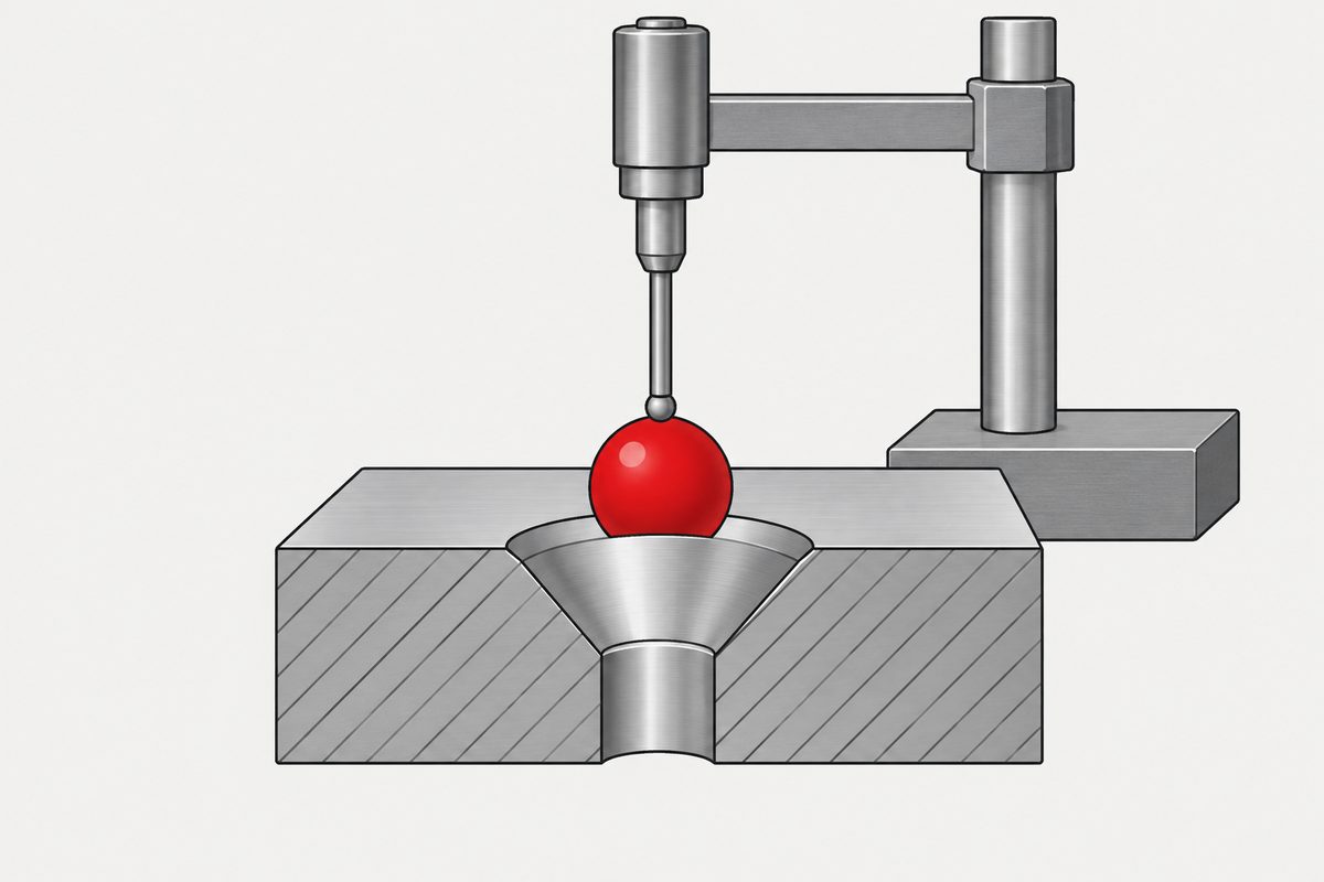
Two hundred machinists, and almost nobody measures the angle
There is a thread on r/Machinists asking how people measure countersink diameters. It ran to 244 comments. The top-voted answer, by a wide margin, was a joke: “I use my Eyecrometer.”
Push the joke aside and the serious answers fall into four groups — optical comparator, a dedicated countersink gauge, a gauge ball with a height gauge, and the inside jaws of a caliper. They disagree about accuracy and cost. They agree about something more interesting, which nobody in the thread says out loud: not one of them measures an angle.
Why not: the apex is not there
An angle needs two surfaces and the line where they meet. In a countersink the cone is real but its apex is virtual — it sits below the part, at the point where the cone would close if the hole did not interrupt it. You cannot put a caliper on it, and a protractor laid across the top is reading the chamfer of your own instrument as much as the part.

So the angle gets converted into a length. That is the whole trick, and every method is a different way of doing it:
| Method | The quantity it reads |
|---|---|
| Countersink / chamfer gauge | Diameter at the surface, read directly |
| Gauge ball + height gauge | How far the ball stands above the face |
| Caliper inside jaws | Diameter at the surface, by eye |
| Optical comparator | A profile, from which a diameter is taken |
One note on the comparator, because it is the method people assume is effortless: on a whole part, a backlight only silhouettes the outline. To see the rim of the countersink you generally need surface reflected illumination, and the part square to the lens. It is accurate, not automatic.
The ball method, and why it works
Drop a ball of known diameter into the cone. It cannot reach the apex, so it settles touching the cone on a circle, and it stands some height above the face. Measure that height and the surface diameter follows from trigonometry.
With ball diameter D, included angle 2α, and h the height the top of the ball stands above the face:
d = D / cos α + (D − 2h) · tan α
The derivation is short enough to be worth seeing, because it explains why the method is exact rather than approximate. The ball centre sits on the cone axis. Its perpendicular distance to the cone surface must equal the ball radius R, which puts the centre at height R / sin α above the virtual apex. The face is a further R − h above that. The cone radius at any height is that height times tan α, and doubling gives the diameter.
Notice what the derivation needed: the position of the apex that you cannot touch. The ball finds it for you. That is the reason a shop keeps a card of pre-computed ball heights taped inside the toolbox rather than a protractor.
It fails in three ways worth knowing. A ball too small for the angle sinks until it touches the drilled hole below instead of the cone. A ball too large rides on the outer edge, or on the deburring chamfer, and never contacts the cone at all. And a burr on the rim lifts the measured height without changing the part.
When you do need the angle itself
Everything above is about the diameter, because that is what production varies and what the shop actually checks. But the title of this page overstates one thing, and it is worth being exact about it: the angle is not unmeasurable. It is unmeasured. Those are different claims, and the difference matters when an incoming batch is disputed.
The apex being virtual does not actually prevent measurement. A coordinate measuring machine, a contour tracer or a 3D optical system fits a cone to many points on the real conical surface and reports the included angle, the axis, the diameter at a stated plane, the depth and the form. None of that needs the apex to exist as a touchable feature — the surface is enough, and the apex falls out of the fit. So the honest reason the shop does not measure the angle is not that it is impossible; it is that the instruments which can are not the ones on the bench, and the angle was fixed by the tool anyway.
There is a bench method that does give the angle, and it is the same trick as the ball above, run twice. Seat two balls of different radii in the same cone. Each settles at a height governed by the cone angle, so the difference between them contains the angle and nothing else. With radii R1 and R2 and axial ball-centre positions C1 and C2 from the same datum:
|C2 − C1| = |R2 − R1| ÷ sin α ⇒ 2α = 2 arcsin( |R2 − R1| ÷ |C2 − C1| )
Those are ball-centre positions, not ball tops. If your indicator reads the top of each ball, convert to centres first by subtracting each radius. Dropping the raw difference of top heights into this formula introduces an error equal to the difference in radii — and the two balls are deliberately chosen to have different radii, so that error is never zero. Sphere methods for internal tapers are long established and appear in the NIST dimensional metrology literature.
The same three failure modes apply, plus one more: both balls have to contact the same undamaged band of cone, and neither may bottom out in the drilled hole below. Ordinary cylindrical pins are not a drop-in substitute for balls, because their contact geometry differs and has to be modelled specifically.
And here is the trap that makes this worth knowing at all. A dial countersink gauge converts axial displacement into a diameter at an assumed angle. It does not verify that angle — it presupposes it. So a countersink cut with the wrong tool can read perfectly in tolerance on a diameter gauge. If a part passes the gauge and still will not seat, the angle is the thing nobody checked, and a diameter gauge will never find it.
The method most people actually use is not a measurement
Read that thread again and the single most repeated answer is not an instrument. It is: take the screw that goes in the hole, put it in, and see whether the head sits flush or below.
It is tempting to file that under shortcuts. It is not one. Those people are checking a different thing: not whether the hole is the size on the drawing, but whether the assembly works. If the requirement is that nothing protrudes above the surface, a screw is a more direct test of that requirement than a diameter is. As one commenter put it, if the head is below flush, it is good to go.
So when does it stop working? When the drawing stops asking a functional question and starts asking a dimensional one.
What the screw does not tell you
Another commenter, with 75 votes, warned that flat head screw diameters vary drastically between manufacturers and materials. He is right, and this is the part we can put numbers on, because it is our side of the fence.
ISO 10642 (hex socket countersunk head screws; the current edition is the fourth, published March 2026) gives head diameter three separate ways, and confusing them is the classic error. dk,theor,max is the theoretical sharp diameter where the cone would meet the top face if both continued — a construction dimension, not something you find with a caliper. dk,actual max and min bound the real outer edge of a finished screw. The tolerance band is the spread of the actual pair, not the gap between theoretical and actual.
| Size | dk theor. max | dk actual max | dk actual min | Band |
|---|---|---|---|---|
| M3 | 6.72 | 5.81 | 5.54 | 0.27 |
| M4 | 8.96 | 7.96 | 7.53 | 0.43 |
| M5 | 11.20 | 10.07 | 9.43 | 0.64 |
| M6 | 13.44 | 12.16 | 11.34 | 0.82 |
| M8 | 17.92 | 16.43 | 15.24 | 1.19 |
| M10 | 22.40 | 20.69 | 19.22 | 1.47 |
Now put a tolerance on the hole. Take a drawing calling the countersink diameter at ±0.005 in — a total band of 0.254 mm. That is the example this article uses; we are not claiming it as an industry norm.
At M3, the screw head band is 0.27 mm — barely wider than the feature you are checking. At M6 it is more than three times wider. At M10, 1.47 mm against 0.254 mm, close to six times. A screw of unknown head diameter cannot resolve a feature whose whole tolerance is a fraction of the screw's own permitted range.
The honest version is narrower than “screws are not gauges”. The table is the envelope of screws that are all conforming; a single batch will not scatter across the whole of it. A screw you have measured is a legitimate comparison piece or setup aid. What fails is the untraced screw out of the bin used as evidence of conformance — and the failure gets worse as the screw gets bigger.
Where the angle number does come from
Since you never measure it, it is worth being precise about where it is decided. 82° with inch flat heads and 90° with metric is a convention, not a rule — ASME B18.6.3 itself covers both 82° and 100° countersunk heads. 100° is well established in aerospace fastening, and 120° appears in aerospace and military practice too.
The standards divide the work: ISO 7721 defines the head geometry, including the distinction between theoretical and actual outer edge that the table above depends on. ISO 10642 gives the dimensions for that particular product. ISO 15065 and DIN 74 specify the hole — the countersink itself, not the screw. If your drawing and your supplier are arguing, it is usually because one of you is quoting a screw standard at a hole question.
That is worth making concrete, because the clauses people reach for in this argument are mostly not about the hole at all:
| Clause | What it actually inspects |
|---|---|
| ISO 7721:1983 §3 | The manufactured screw head — its top must lie between gauge surfaces A and B. Not the hole |
| ISO 7721-2:1990 | Cross-recess penetration depth. Not an angle method at all |
| ASME B18.6.3 Mandatory Appendix I | Protrusion gauging of the manufactured head against a sharp-edged ring gauge. Not a production hole |
| ISO 15065:2005 §3 | The hole: angle, major countersink diameter, clearance hole diameter, approximate depth, coaxiality |
Three of those four inspect the screw. Only the last one is about the feature being cut. So when a supplier answers a hole question by citing a gauging clause, the clause is often perfectly real and perfectly irrelevant — and the argument goes in circles because both sides are right about different parts.
The complaint that gives the game away
One machinist in that thread cursed the engineer who put a ±0.005 in countersink diameter on a part made from stock-thickness material. He was pointing at something real.
The surface diameter of a countersink is set by how deep the tool goes below the face it breaks out of. If the machine takes its Z reference from the back of the plate and the plate thickness varies, then the depth below the front face varies with it — and the diameter moves. The geometry did not change; the datum did.
The fix is not simply to declare the front face a datum on the drawing. That controls how the part is inspected, not how the machine found Z. What actually removes the coupling is referencing Z from the countersunk face at the machine — or accepting that the diameter is the thing that matters and inspecting it directly, which brings you back to the top of this page.
So which do you do
The question to ask first is not how do I measure this. It is why is this dimension controlled at all.
If the requirement is that the head does not stand proud, the screw is the right check, and reaching for a gauge is measuring something the drawing does not care about. If the requirement is a dimension — because a seal lands there, because the head has to bury to a stated depth, because the customer's print says so — then you need the diameter, and you need it from something traceable. Two different acceptance methods, because they are accepting two different things.
Choosing the angle in the first place is a separate decision, and it is usually not yours to make. Where this fits in the wider order of decisions is covered in specifying a screw.
References
- ISO 10642:2026 — Hexagon socket countersunk head screws (fourth edition, March 2026; supersedes ISO 10642:2019)
- ISO 7721:1983 — Countersunk flat head screws: head configuration and gauging; §3 gauges the manufactured head between surfaces A and B
- ISO 7721-2:1990 — penetration depth of cross recesses (not an angle method)
- ASME B18.6.3 Mandatory Appendix I — protrusion gauging of the manufactured head against a sharp-edged ring gauge
- ISO 15065 / DIN 74 — Countersinks for countersunk head screws (the hole)
- ASME B18.6.3 — Machine screws and tapping screws (inch, 82° and 100°)
- Thread on measuring countersink diameters, r/Machinists, 244 comments
This page describes measurement practice and the geometry behind it. Acceptance criteria for any particular part are governed by your drawing and the standards it invokes.
This page covers step 3, the head. The whole order is substrate, thread, head, drive, finish, documentation, and why doing it out of order is rework rather than a tweak is in specifying a screw.
Common questions
How do I measure a countersink angle?
In practice you do not. The apex of the cone is a virtual point below the part, so there is nothing to put an instrument on. The angle is fixed by the tool you cut with. What gets measured is the diameter at the surface, either directly with a countersink gauge or comparator, or indirectly by seating a ball in the cone and measuring how far it stands above the face.
What is the gauge ball formula for a countersink?
With ball diameter D, included angle 2 alpha, and h the height the top of the ball stands above the face, the surface diameter is d = D / cos alpha + (D minus 2h) times tan alpha. It is exact, not an approximation, because the ball locates the virtual apex that you cannot reach.
Can I just use the screw to check a countersink?
For a functional requirement, yes, and it is a more direct test than a diameter. For a dimensional tolerance, no. ISO 10642 permits head diameters spanning 0.27 mm at M3 and 1.47 mm at M10, so an untraced screw cannot resolve a feature toleranced tighter than that. A screw you have measured yourself is a legitimate comparison piece.
Are inch countersinks always 82 degrees and metric always 90?
That is the common convention but not a rule. ASME B18.6.3 covers both 82 and 100 degree countersunk heads. 100 degrees is well established in aerospace, and 120 degrees appears in aerospace and military practice.
Why does my countersink diameter drift on stock-thickness parts?
Because the surface diameter depends on how deep the tool goes below the face it breaks out of. If Z is referenced from the back of the plate and the plate thickness varies, the depth below the front face varies with it. Referencing Z from the countersunk face at the machine removes the coupling; declaring that face a datum on the drawing alone does not.
Enquiries
We make countersunk screws, so we spend a lot of time on the other half of this fit. If a print and a sample are disagreeing, send us both — the drawing callout and what you are measuring — and we will tell you which side the difference is on.
Request a quotation
Tell us the part and the quantity. We will come back on feasibility, lead time and price.
Or email us directly sales@tigerfasteners.com