 TIGERFASTENERS
Countersink, counterbore, spotface — and why the callout is not the same in both systems
A hole callout looks like a small thing to get right. It is three features that are constantly swapped for each other, two standards systems that do not share a syntax, and one symbol that half the internet attributes to the wrong feature.
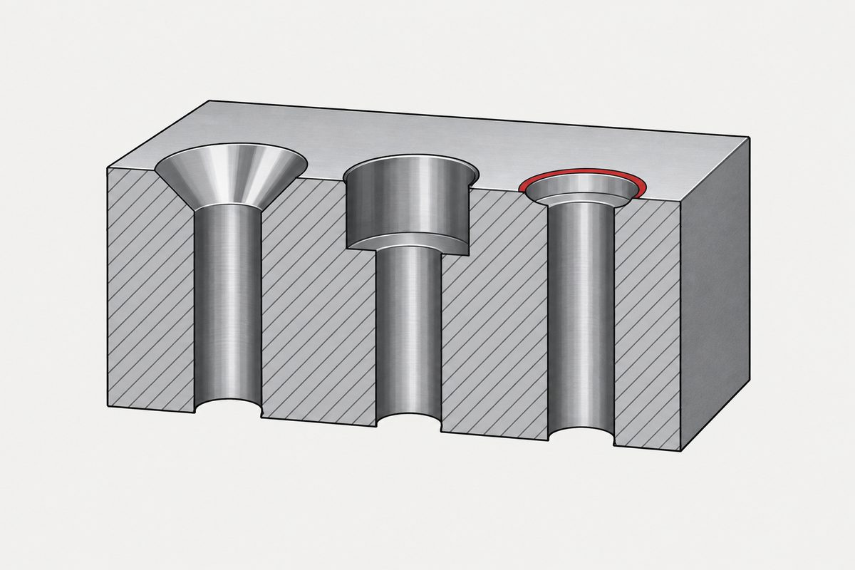
Three features, and what actually separates them
- Counterbore — a coaxial cylindrical enlargement with a nominally flat bottom. ISO's precise term is “cylindrical counterbore, flat hole bottom”. Fully recessing a fastener head is the usual reason for one, not part of the definition; whether the head disappears depends on the depth you specify.
- Countersink — conical, a circular chamfer at the entrance, defined by diameter and included angle.
- Spotface — a shallow machined flat. ASME Y14.5-2018 clause 4.5.14 says that when no depth or remaining thickness is given, it is machined only to the minimum depth needed to clean up the surface to the stated diameter. Seating a head or washer is the common purpose; the standard defines it by the clean-up, not by the purpose.
Which angle a countersink should be, and why that was decided somewhere other than your drawing, is in it looks like a choice.
The ASME symbols, and one date worth knowing
ASME Y14.5-2018 (R2024) — the R means reaffirmed in 2024, not a new edition — puts the hole requirements at clauses 4.5.10 to 4.5.14 and the symbols at 6.3.12 to 6.3.15:
| Feature | Symbol | Official name | Clause |
|---|---|---|---|
| Counterbore | ⌴ | Counterbore Symbol | 6.3.12 |
| Spotface | SF in a box | Spotface Symbol | 6.3.13 |
| Countersink | ⌵ | Countersink Symbol | 6.3.14 |
| Depth | ↧ | Depth Symbol | 6.3.15 |
A conventional ASME countersink callout, from Figures 4-37 and 6-17:
∅6.5 THRU
⌵∅10 × 90°
The boxed SF is older than people think. It arrived in ASME Y14.5-2009, not 2018. In Y14.5M-1994 the glyph at clause 3.3.12 was officially called the “Counterbore or Spotface Symbol” — one symbol served both features. The 2009 edition split them into separate clauses, and 2018 kept the split. So a drawing that uses the counterbore symbol for a spotface is not necessarily wrong; it may be following a 1994-era standard.
ISO does not simply use the same symbols
This is where we had it wrong. There are two separate ISO practices, and neither is a translation of ASME.
ISO 15786:2008, Technical drawings — Simplified representation and dimensioning of holes (confirmed 2024), uses a structured textual notation with suffix letters. In its Table 2, U is the symbol for “cylindrical counterbore, flat hole bottom”. Size and depth are separated by ×, not by the ASME depth glyph.
ISO 129-1:2018 (with Amendment 1:2020) is the dimensioning standard, and it defines graphical property indicators named “cylindrical counterbore”, “countersink” and “depth” in Table 1 and clause 7.1. Those look like the ASME glyphs. The rules around them, the permitted formats, and the treatment of spotfaces still differ.
V is not the ISO countersink symbol. It appears that way in a lot of CAD forum posts and copied reference sheets. In ISO 15786:2008 Table 2, V officially means “material-dependent bit — point angle of hole bottom”. It describes the cone left at the bottom of a drilled blind hole by the drill point. It is not the cone at the entrance.
And we could not find a dedicated spotface symbol or SF property indicator in ISO 15786:2008 or ISO 129-1:2018 at all. Guidance claiming ISO requires the boxed SF appears to have been copied across from ASME.
The order is not the machining order
The tidy explanation is that the callout reads in the order the machinist works: drill the through hole, then open the counterbore. We were going to write that. It has no basis in either standard.
ASME clauses 4.5.11 and 4.5.12 show a conventional presentation order and give no process rationale. Y14.5 defines the product, not the sequence of operations.
ISO 15786 is direct evidence against it. Clause 5.1 orders the features of a simplified hole callout by size, largest dimension first — which can be the reverse of the drilling order. Clause 4.3 does mention that the leader arrow indicates the surface features are worked from, but that is a direction, not a chronology.
The honest sentence is that the order is a standardised description of a compound feature, not a mandatory machining sequence. Which also means a supplier reading an ISO simplified callout and an ASME callout is reading two differently-ordered descriptions of the same geometry.
Diameter or angle: both
ASME clause 4.5.12's ordinary method specifies the countersink diameter and included angle. Other fully defining combinations are permitted. ISO 129-1 clause 7.1 and Annex B.2 allow largest diameter plus included angle, or depth plus included angle, or the plan-view property indicator with surface diameter plus included angle.
The included angle survives every one of those alternatives. So “flush seating depends on the diameter, not the angle” is wrong, and it was in our draft. A wrong angle can leave the head on line contact or edge contact even when the surface diameter is exactly right. Neither standard says diameter is preferred because it is easier to measure — that was an inference of ours with nothing behind it.
What a mismatch between the head's angle and the hole's costs you is worked through in what a few degrees actually does, and the dimension side of it is in two documents, two conventions, one symbol.
What goes wrong in practice
- “CSK” with no values. That names the feature type and specifies nothing about its size. CSK is also an abbreviation rather than the official symbol name, so whether it is acceptable at all depends on the drawing's abbreviation list or the company drafting standard.
- Counterbore written where a countersink is meant, or the reverse. One is cylindrical and one is conical. The parts that result are not interchangeable and neither is the screw that goes in them.
- A spotface with no depth. Under ASME that is a defined condition, not an omission: clean up to the minimum depth. If you needed a specific depth, say so.
- A countersink deeper than the plate. On thin sheet the cone can break through before it reaches the diameter you asked for. The interaction with head height is in thinner and smaller heads leave less to work with.
- No statement of which system the drawing follows. Given the syntax differences above, this is not a formality.
For a supplier in Taiwan, both systems arrive
Taiwan has CNS drawing standards, and we looked for evidence about which system the industry actually follows. We could not find an authoritative survey. Practice appears to depend on the customer, the export market, the company's own drafting manual and the sector — which is a real answer, not an absence of one.
The practical consequence for anyone quoting or making to a drawing here is that both systems land on the same desk. An ASME drawing from a US customer and an ISO simplified callout from a European one describe the same hole with different symbols in a different order. So:
- Put the governing standard and its year in the title block, not just “ISO” or “metric”.
- If you inherit a drawing that uses the counterbore symbol for a spotface, check the edition before calling it an error.
- If a callout uses a bare letter, confirm which table it came from before assuming it means what a forum post said.
Where this connects
The angle itself is in countersunk angles, the dimensions in countersunk hole dimensions, and what happens when several of these tolerances land on the same joint is in tolerance stack-up.
References
- ASME Y14.5-2018 (R2024), Dimensioning and Tolerancing — clauses 4.5.10 (round holes), 4.5.11 (counterbored), 4.5.12 (countersunk and counterdrilled), 4.5.13 (countersinks on curved surfaces), 4.5.14 (spotfaces), 6.3.12–6.3.15 (symbols); Figures 4-34 to 4-39 and 6-16 to 6-18
- ASME Y14.5-2009 — clauses 3.3.12 and 3.3.13, where the counterbore and spotface symbols were first separated; ASME Y14.5M-1994 clause 3.3.12, “Counterbore or Spotface Symbol”
- ISO 15786:2008 (confirmed 2024), Technical drawings — Simplified representation and dimensioning of holes — clause 1 (scope), 5.1 (ordering by size, largest first), 5.2 and Table 2 (symbols, including U and V), 4.3 (leader direction)
- ISO 129-1:2018 + Amd 1:2020 — Table 1 and clause 7.1 (property indicators), Annex B.2
- ISO 6410-1:1993 (screw thread representation, general conventions), ISO 6410-3:2021 (simplified representation); the ISO 128 series covers general principles of representation rather than hole callouts
Acceptance for any particular drawing is governed by the standard that drawing invokes.
This page covers step 3, the head. The whole order is substrate, thread, head, drive, finish, documentation, and why doing it out of order is rework rather than a tweak is in specifying a screw.
Common questions
Is V the ISO symbol for a countersink?
No. That attribution circulates widely in CAD forum posts and copied reference sheets, but in ISO 15786:2008 Table 2 the letter V officially means a material-dependent bit, that is the point angle at the bottom of the hole. It describes the cone the drill point leaves at the bottom of a blind hole, not the cone at the entrance where a countersunk head sits.
Do ISO and ASME use the same hole callout symbols?
Not in the way people assume. ASME Y14.5-2018 uses the graphical counterbore, spotface, countersink and depth symbols at clauses 6.3.12 to 6.3.15. ISO 15786:2008 uses a structured textual notation with suffix letters, where U means a cylindrical counterbore with a flat hole bottom and size and depth are separated by a multiplication sign. ISO 129-1:2018 separately defines graphical property indicators that resemble the ASME glyphs, but the permitted formats, the ordering rules and the treatment of spotfaces still differ.
Does the order of a hole callout follow the machining sequence?
No, and one of the standards contradicts it directly. ASME shows a conventional presentation order without giving a process rationale, and it defines the product rather than the sequence of operations. ISO 15786 clause 5.1 orders the features of a simplified hole callout by size with the largest dimension first, which can be the reverse of the drilling order. The order is a standardised description of a compound feature.
Does a flush countersunk head depend on the diameter or the angle?
Both. ASME clause 4.5.12 specifies the countersink diameter and included angle in its ordinary method, and every alternative that ISO 129-1 permits still carries the included angle. A wrong angle can leave the head on line contact or edge contact even when the surface diameter is exactly right.
When was the SF spotface symbol introduced?
In ASME Y14.5-2009, not in the 2018 edition. Before that, ASME Y14.5M-1994 clause 3.3.12 called the glyph the counterbore or spotface symbol, with one symbol serving both features. The 2009 edition separated them into clauses 3.3.12 and 3.3.13 and the 2018 edition kept the separation. A drawing using the counterbore symbol for a spotface may be following the older standard rather than making an error.
What happens if a spotface is called out without a depth?
Under ASME Y14.5-2018 clause 4.5.14 that is a defined condition rather than a missing dimension: the surface is machined only to the minimum depth needed to clean up to the stated diameter. If a particular depth or a particular remaining material thickness matters to the design, it has to be stated explicitly.
Which system do drawings in Taiwan follow?
There is no single answer we could verify. Taiwan has CNS drawing standards, but we could not find an authoritative survey of industry practice, and it appears to depend on the customer, the export market, the company drafting manual and the sector. The practical consequence is that a supplier here receives drawings in both systems, so the governing standard and its year belong in the title block.
Enquiries
If a drawing has a countersink, counterbore or spotface on it, send the drawing rather than a description. The symbol, its order and the standard in the title block all change what we would quote.
Request a quotation
Tell us the part and the quantity. We will come back on feasibility, lead time and price.
Or email us directly sales@tigerfasteners.com