 TIGERFASTENERS
Countersunk hole dimensions: why two charts disagree
The short version: look up the head diameter of an M3 countersunk socket screw in two reputable places and you get 6 mm from one and 6.72 mm from the other. Neither is a typo, and they are not the same document. One is DIN 7991; the other is ISO 10642, which replaced it. They also label the figure differently — nominal against theoretical. Two confounds, stacked, about a millimetre wide at M3. Which means you cannot reconcile them — you have to find out which document your drawing cites.
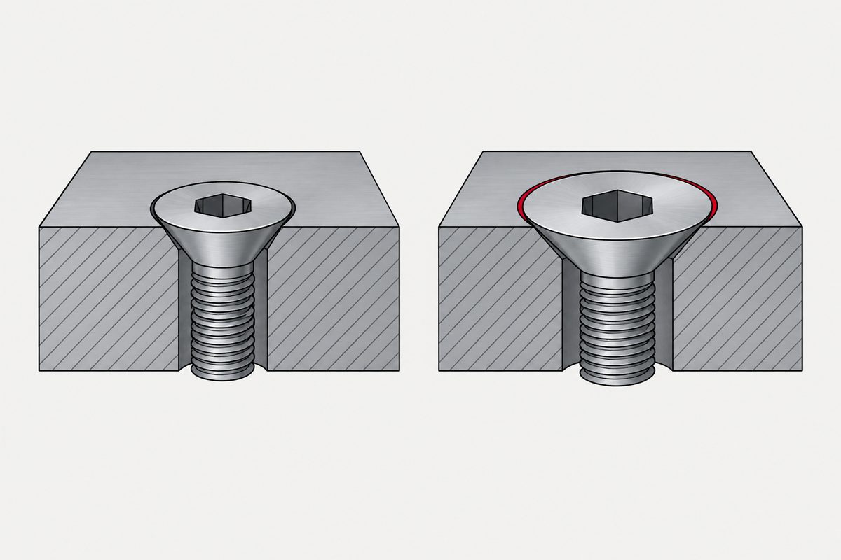
Two documents, two conventions, one symbol
Both are from fastener suppliers and both describe a 90° hexagon socket countersunk head — but they are describing two different standards. Fuller's own page notes that ISO 10642 “Replaces DIN 7991”:
| Size | fasteners.eu DIN 7991 “dk nominal=max.” | Fuller ISO 10642 dk Theoretical / max | Fuller ISO 10642 dk Actual / min |
|---|---|---|---|
| M3 | 6 | 6.72 | 5.54 |
| M4 | 8 | 8.96 | 7.53 |
| M5 | 10 | 11.2 | 9.43 |
| M6 | 12 | 13.44 | 11.34 |
| M8 | 16 | 17.92 | 15.24 |
| M10 | 20 | 22.4 | 19.22 |
We are reproducing what each source prints, not certifying either. The Fuller figures sit under a Theoretical row and an Actual row rather than in one combined header, so the labels above are our compression of its table, not a single verbatim string. Two things differ at once here, and we cannot separate them from these two pages alone: the standards are different documents, and the reporting conventions are different. Published comparisons of DIN and ISO countersunk heads report that head dimensions changed between them — so attributing the whole gap to labelling would be wrong.
The symbol itself is not shared across the two standards systems either — two callout systems.
What “theoretical” is measuring
A countersunk head is a cone. If you let that cone run all the way out until its surface meets the top face at a sharp corner, you get one diameter. Real heads do not have that corner — the edge is broken or rounded — so the metal stops short of it. The theoretical figure describes the sharp-cornered cone that is never manufactured; the nominal and actual figures describe the part that is.
That is why a theoretical figure is a construction dimension rather than something a caliper will confirm, and it is the wrong number to hand to whoever is cutting the hole. But note the limit of this explanation: it accounts for the gap between ISO 10642's own theoretical and actual columns. It does not account for the gap against DIN 7991, because that is a different document. Neither source page explains the cross-standard difference, and we are not going to invent a reason.
Why a millimetre matters here
The countersink and the head have to seat on each other across the whole cone. Cut the countersink to a top diameter derived from a theoretical head and the hole is wider than the head needs, so the head drops in further than intended and can sit below flush — in thin sheet, it can break through into a knife edge at the bottom of the countersink. Derive it the other way and the head stands proud.
This is the same failure the angle mismatch produces, arriving through the diameter instead: contact that was supposed to be spread over a cone collapses onto a circle. The angle is the more stable half, but it is not a single number per system: ISO 10642 specifies 90°, while inch ASME B18.6.3 covers both 82° and 100° flat countersunk head machine screws — so naming that standard without the angle is not enough either.
Where to get the number that governs
Not from a chart, including this one. In order of authority:
- The countersink standard the drawing cites — the head standard dimensions the screw; a countersink standard dimensions the hole, and the hole is what you are machining. DIN 74 form F is the one that covers the ISO 10642 hexagon socket countersunk head. ISO 15065 is also a countersink standard, but its stated applicability list does not include ISO 10642 — so check that the countersink standard you cite actually covers the head you are using.
- The supplier's dimensioned drawing for the actual part — which is what we will send if you ask. Below M6 especially, head geometry is where catalogue figures and delivered parts most often part company.
- A published chart — useful for sanity-checking an order of magnitude, and for nothing that gets cut.
Specify the countersink by its top diameter and angle directly rather than deriving it from dk, and the ambiguity above never enters your drawing. Related: what a size chart cannot tell you for the same problem in the thread series, and where standards stop for the sizes below which the tables run out entirely.
Common questions
Why do two countersunk screw charts give different head diameters for the same size?
Partly because they are not the same standard. Fasteners.eu publishes DIN 7991 and gives 6 mm at M3; Fuller Fasteners publishes ISO 10642, which its own page notes "Replaces DIN 7991", and gives 6.72 mm. On top of that the two label the figure differently — "dk nominal=max." against a "Theoretical" row and an "Actual" row. Two confounds sit on top of each other, so the gap cannot be attributed to labelling alone, and neither number is safe to copy into a drawing that cites the other document.
Which number should I use to machine a countersink?
Start by establishing which standard the drawing actually cites, because DIN 7991 and ISO 10642 are different documents and one replaced the other. Then take the countersink from the countersink standard rather than from the screw's head table — DIN 74 form F covers the ISO 10642 hexagon socket countersunk head — or from the supplier's dimensioned drawing for the actual part. Specify the countersink's top diameter and angle directly instead of deriving them from dk.
Is dk the diameter I will measure on a real screw?
Not where a chart labels it theoretical. In ISO's usage a theoretical diameter is a construction dimension for the sharp-cornered cone, and the real head has a broken edge, so a caliper will read less. Where a chart labels dk nominal or max it is closer to a measurable limit, but it is still a limit and not a target.
Does this affect the countersink angle as well?
Less, but do not assume a single number per system. ISO 10642 specifies 90 degrees. On the inch side ASME B18.6.3 is not a single angle — it covers 82 degree and 100 degree flat countersunk head machine screws — so citing the standard without the angle is not enough. Angle and diameter still have to be specified together, because the pairing is what seats the head.
What should go on the drawing so this cannot happen?
Name the head standard, its edition and its angle; name the countersink standard separately with the countersink angle and its top diameter; and state the flushness acceptance criteria. Also check the sheet is thick enough for the head height, so the countersink does not break through and leave a knife edge.
References
- fasteners.eu — DIN 7991 hexagon socket countersunk head cap screws column header “dk nominal=max.”, retrieved 2026-08-22
- Fuller Fasteners — ISO 10642 specifications rows “dk Theoretical max” and “dk Actual min”, retrieved 2026-08-22
- DIN 74 (form F for ISO 10642) and ISO 15065 dimension the countersink itself; ISO 7721 covers countersunk head configuration and gauging. We were not able to retrieve any of these from the standards bodies directly — confirm scope and current edition with your standards body before releasing a drawing.
This page covers step 3, the head. The whole order — substrate, thread, head, drive, finish, documentation — and why doing it out of order is rework rather than a tweak, is in specifying a screw.
Enquiries
Send the drawing and we will send back the head geometry we would actually produce to, with the countersink dimensions we would expect on the mating part. sales@tigerfasteners.com
Request a quotation
Tell us the part and the quantity. We will come back on feasibility, lead time and price.
Or email us directly sales@tigerfasteners.com