 TIGERFASTENERS
Metric or Inch? The Pitch Will Not Separate #10-32 from M5
Someone hands you a screw with no drawing and asks what it is. Two rules circulate on the shop floor: measure the diameter, or measure the pitch. Both are right some of the time, and knowing which is which is the whole skill.
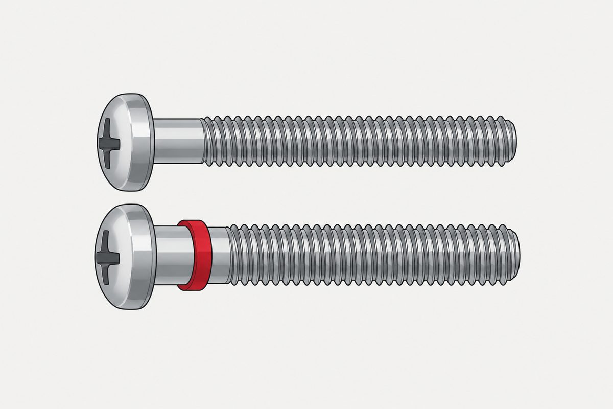
Corrected 26 August 2026. The first version of this page argued that the diameter was the one measurement that could separate #10-32 from M5×0.8. A fact-check showed that is wrong once real tolerance bands are used — they close to 0.023 mm — and that several other claims here were overstated: 0.0625 mm is not below caliper resolution, spanning more threads does improve the measurement, the mismatched screw starts loose rather than tight, and it may pass through a short nut without binding at all. Those passages have been rewritten rather than removed, and the answer is now the pitch diameter.
Two rules that contradict each other
The first rule says the diameter tells you: an inch screw lands on an odd millimetre number, so 6.35 mm is a quarter inch and 6.00 mm is M6. The second says the diameter is unreliable because tolerance and plating move it, so measure the pitch instead.
Both pieces of advice are common, and they are usually given as though they were general rules. They are not. Which measurement can separate two candidates depends entirely on which two candidates you are holding, and there is at least one common pair where the popular rule is simply useless.
The four pairs that actually get confused
Inch major diameters come from a simple formula for numbered sizes — the major diameter is 0.060 in plus 0.013 in per number, so a #10 is 0.190 in — and the pitch is the reciprocal of the threads-per-inch count. Put the four common near-misses side by side in millimetres:
| Pair | Major dia. difference | Pitch difference | What can separate them |
|---|---|---|---|
| 1/4-20 UNC vs M6×1.0 | 0.350 mm | 0.270 mm | either |
| 1/4-28 UNF vs M6×1.0 | 0.350 mm | 0.093 mm | diameter is the safer one |
| #10-24 vs M5×0.8 | 0.174 mm | 0.258 mm | pitch is the safer one |
| #10-32 vs M5×0.8 | 0.174 mm | 0.006 mm | neither, with a caliper |
Read the third and fourth rows together. They involve the same two nominal sizes, and they reverse which instrument is trustworthy. That is why neither folk rule survives as a general rule.
#10-32 and M5×0.8: a pitch difference of 0.006 mm
A 32 threads-per-inch pitch is 25.4 ÷ 32 = 0.79375 mm. The metric coarse pitch for M5 is 0.8 mm. The difference is 0.00625 mm per thread.
Measuring over ten threads accumulates that to 0.0625 mm. A digital caliper displays to 0.01 mm, so this is not a resolution problem — it is six display increments. The difficulty is everything else: locating the jaws on thread crests, jaw tilt, repeatability, and the accumulated lead error already present in the part, which for a #10-32 UNF-2A class is of the same order as the difference you are hunting.
So the honest statement is narrower than “the pitch cannot be measured”: an ordinary caliper or a short hand pitch gauge is unlikely to settle this pair. Longer measurement does help — the endpoint error stays roughly constant while the distance grows, so spanning more threads genuinely improves the ratio. It is the instrument, not the physics, that runs out.
Why “it screws in” is not evidence
The instinct is to try it in the hole. It is the most misleading test available, but not for the reason people expect. A #10-32 screw in an M5 nut starts loose, not tight. The pitch diameters are 4.211–4.287 mm against an M5-6H nut at 4.480–4.605 mm, so there is between 0.19 and 0.39 mm of diametral slack. It goes in feeling wrong in the wrong direction — sloppy rather than stiff.
Nor does it reliably jam. Treating the 0.00625 mm per thread as an equivalent diametral interference of about 1.732 times the accumulated lead error, binding needs roughly 16 to 36 threads of engagement. An ordinary M5 nut offers about 3 to 9. A mismatched screw can therefore run straight through a short nut without binding at all, which is precisely why the test is treacherous: it can report success. Deep tapped holes are where it does bind.
Whether anything is damaged, and which side, depends on the pairing. A hardened steel screw in an aluminium or plastic boss endangers the female thread; a soft screw in a hard nut can lose its own. Without forcing it, there may be no permanent damage at all. What the test never gives you is a clean answer.
This is the same reason a thread gauge is worth its cost: it answers the question without loading the part. Related: how to read a specification once you know what system it is in.
And the diameter does not rescue it either
Having said the pitch will not settle this pair, the obvious move is to lean on the 0.174 mm difference in diameter. That number is the gap between two nominal sizes, and nominal sizes are not what you measure.
| Major diameter | Pitch diameter | |
|---|---|---|
| M5×0.8-6g | 4.826–4.976 mm | 4.361–4.456 mm |
| #10-32 UNF-2A | 4.651–4.803 mm | 4.211–4.287 mm |
| Closest case | 0.023 mm | 0.074 mm |
The major-diameter bands very nearly touch. A #10-32 at the top of its tolerance and an M5 at the bottom of its own are 0.023 mm apart, and the bottom of the M5 band is 4.826 mm — numerically identical to the #10 nominal. A caliper cannot be trusted to call that.
The pitch diameter is the measurement that does separate them, by 0.074 mm in the worst case. That is a thread micrometer or a three-wire measurement, not a caliper. An optical comparator or a tool microscope reads the pitch directly and settles it too.
There is a reason a go/no-go gauge is the cleanest answer of all, and it is the same reason the pitch has no tolerance column of its own: a pitch deviation is controlled through its effect on the functional diameter, which is exactly what a full-form GO gauge reads. The 0.00625 mm per thread does not disappear — it reappears as diameter, where a gauge can catch it. See why the tolerance table has no column for pitch.
One correction to a common intuition, including the one this article previously printed: plating and tolerance do not both close the gap. Zinc adds roughly 0.010–0.024 mm to a major diameter, which pushes a plated #10 upwards and towards M5. But external thread tolerance runs downwards from the basic size for both threads, so a #10 low in its band moves away from M5, not towards it. The effects act in different directions, and plated parts are dimensioned before coating in any case — see why the tolerance has to set aside room for the coating.
So what do you actually do
The workable procedure is not a single measurement but an order of operations:
- Measure the major diameter first and use it to produce a shortlist, not an answer. It rules out most candidates cheaply.
- Then measure the pitch over ten threads — over ten, because your reading error divides by ten while the quantity you are measuring multiplies by ten.
- Check whether a caliper can separate the candidates left at all. This is the step everyone skips. For #10-32 against M5×0.8 it cannot: the pitches are 0.006 mm apart and the major-diameter bands close to 0.023 mm.
- If it cannot, change instrument rather than trying harder. The pitch diameters stay 0.074 mm apart, so a thread micrometer, a three-wire measurement, an optical comparator or a go/no-go gauge of a stated designation will settle it. What does not work is more care with the same caliper.
The real answer is not on the bench
When step four is reached, the question stops being metrological and becomes documentary. The screw came from somewhere: a drawing, a bill of materials, a supplier, a machine built in a country with a house standard. That provenance resolves the ambiguity in a way that no caliper can, because it is the only source of the information the part itself no longer carries.
This is the argument for writing the thread designation on the drawing rather than a bare size, and it is why the documentation step exists at all — see where the standard stops and your drawing has to start. An identification problem on the bench is almost always a documentation failure that happened earlier, somewhere upstream.
This is not one of the six steps. It shows up across them, or after assembly. Where the decisions that lead here were made is in specifying a screw, which sets out the order and why doing it out of order is rework.
Common questions
Will a #10-32 screw really thread into an M5 nut?
It will, and it starts loose rather than tight — the pitch diameter of a #10-32 UNF-2A is 4.211 to 4.287 mm against 4.480 to 4.605 mm for an M5-6H nut, leaving 0.19 to 0.39 mm of diametral slack. Nor does it reliably bind: the 0.00625 mm per thread needs roughly 16 to 36 threads of engagement to interfere, and an ordinary M5 nut offers about 3 to 9, so the screw can pass straight through without jamming. Deep tapped holes are where it binds. Whether anything is damaged, and which thread goes first, depends on the relative hardness of the two parts.
Can a caliper actually resolve 0.174 mm?
It can display it — 0.174 mm is well above the 0.01 mm a digital caliper shows. The problem is that 0.174 mm is the gap between two nominal sizes, and real parts occupy tolerance bands: M5x0.8-6g runs 4.826 to 4.976 mm and #10-32 UNF-2A runs 4.651 to 4.803 mm, so the closest legitimate pair is 0.023 mm apart. That is not a caliper decision. The pitch diameters remain 0.074 mm apart, which is why the instrument to reach for is a thread micrometer rather than a more careful caliper reading.
Why measure the pitch over ten threads instead of one?
Because the error in placing the caliper jaws is roughly constant regardless of how many threads you span, while the distance being measured grows in proportion. Spanning ten threads therefore divides the per-thread reading error by ten while the signal grows tenfold, so the ratio genuinely improves — and it keeps improving with length. What limits it is not that improvement but systematic error: the accumulated lead deviation permitted in the part itself, which for a #10-32 UNF-2A class is of the same order as the difference being sought.
Does a thread gauge settle it?
A pitch gauge settles every pair in the table except #10-32 against M5x0.8. A hand gauge is a comparison tool with no single published fit tolerance, so the honest statement is that a short leaf held against a 0.00625 mm per thread difference is unlikely to be conclusive, not that it is provably incapable — over ten threads the 0.0625 mm can show as a light gap given good lighting and enough contact length. For a decision you can record, use a go/no-go thread gauge of a stated designation, which tests the whole form rather than one dimension.
References
- ASME B1.1 — Unified Inch Screw Threads (UN, UNR and UNJ Thread Form)
- ISO 261 — ISO general purpose metric screw threads: General plan
- ISO 965-1:2026 — ISO general purpose metric screw threads — Tolerances — Part 1
Nominal diameters and pitches are computed from the definitions in these standards: numbered inch major diameter = 0.060 in + 0.013 in per number, pitch = 25.4 mm divided by threads per inch, metric coarse pitches from ISO 261. Tolerance bands quoted for M5x0.8-6g, M5-6H and #10-32 UNF-2A are the published limits for those classes, and the binding estimate treats accumulated lead error as an equivalent diametral interference of 1.732 times that error.
Enquiries
If you are holding a sample and cannot resolve what it is, send us the part rather than the number. We would rather measure it than have a shortlist guessed at, and for the #10-32 against M5 case the measurement that settles it is not one anyone should be doing with a caliper.
Request a quotation
Tell us the part and the quantity. We will come back on feasibility, lead time and price.
Or email us directly sales@tigerfasteners.com