 TIGERFASTENERS
Left-hand threads: the bicycle pedal explanation predicts the wrong hand
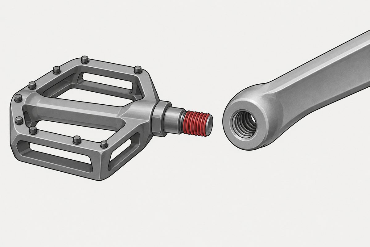
Almost everyone can name one left-hand thread — the left bicycle pedal — and almost every explanation of it predicts the wrong hand. The standards side is less famous and more useful: there is a designation format most people get slightly wrong, and a physical marking requirement most drawings never mention.
How it is actually written
The suffix is LH, and ISO separates it with a dash.
| Source | Form |
|---|---|
| ISO 965-1:2026 §13.4 | M10 × 1,5 - LH, or with tolerance class M10 × 1,5 - 6g - LH |
| ISO 965-1:2013 §12.4 (previous) | Same rule; example M8 × 1 - LH |
| ISO 6410-1:1993 §4.1, §4.4 | Drawing representation; example M20 × 2 - 6G/6h - LH |
So M10 × 1.5 LH reads fine to an engineer, but the ISO typography is M10 × 1,5 - LH. The decimal comma or point follows the document's language.
Right-hand threads are not normally marked. ISO 6410-1 §4.4 says right-hand generally need not be shown, left-hand must carry LH, and where one part has both, both must be marked. RH may be added where it helps.
The marking on the part itself, which is easy to miss
ISO 898-1:2013 §10.3.4 requires left-hand bolts and screws at d ≥ 5 mm to carry a left-pointing arrow on the top of the head or on the end; hex heads may use an alternative groove marking instead (Figures 15–16). ISO 898-2:2022 §11.5 does the same for nuts within its scope (Figures 10–11).
This is not a universal drawing rule — it applies where those product, material and property-class standards apply. But it is the reason a left-hand fastener can often be identified in the hand, and it belongs with the rest of what gets stamped on a head: see what the markings on a bolt head mean.
The bicycle pedal, and why the usual explanation cannot be right
The story everyone tells: the left pedal has a left-hand thread because pedalling would otherwise unscrew it. If you mean the bearing friction torque, that explanation predicts the opposite hand.
Viewed from the left of the bike, pedalling forward:
- the pedal body turns roughly clockwise relative to the spindle;
- bearing friction therefore drags the spindle clockwise;
- clockwise is the tightening direction for a right-hand thread, and the loosening direction for a left-hand one.
So bearing friction alone predicts that the left side should use a right-hand thread. Sheldon Brown's technical page states this directly: bearing friction actually tends to loosen the threads as currently specified, in the opposite direction to precession, and the effect is smaller.
The mechanism that does point the right way is mechanical precession. The rider's radial load rotates around the spindle. Under elastic deformation and fit clearance, the thread flanks, the shoulder and the crank face undergo very small contact micro-slip — fretting. The resulting precession runs opposite to the load's orbit, which on the left crank walks a right-hand thread loose and a left-hand thread tight.
How well is that established? A COMSOL multibody contact model reproduces the mechanism and its direction, and a patent background (EP 3 434 573 A1) states plainly that the pedal thread hands exist to prevent precession-driven loosening. Jobst Brandt's engineering account explains the elastic micro-motion. But we found no peer-reviewed measurement of pedal thread precession, and no technical explanation from Shimano or Campagnolo — Campagnolo's manual states the left crank is 9/16″-20 left-hand and gives no reason. Treat the direction as well argued and the quantitative case as unfinished.
The picture of the axle rolling around the inside of the hole like a wheel in a drum is a simplification. The contact motion is very small and elastic, not a loose axle rattling round a bore.
The three uses that hold up
| Use | Standard |
|---|---|
| Paired adjustment | ASTM F1145-05(2022) §7.3.2–7.3.3 — turnbuckle body has RH one end and LH the other, so turning it moves both ends together |
| Non-interchangeable identification | ISO 5145:2017 §7, Tables 4–5 — gas cylinder outlets in groups 6 to 9 use left-hand threads to stop incompatible connections |
| Directed running torque | ISO 11148-7:2012 §4.2.7 and ANSI B7.1-2010 §3.4.1 — grinder spindle threads chosen so the nut or collet self-tightens with rotation |
Two qualifications. “Flammable gas is always left-hand” is too broad: acetylene sits in ISO 5145's group 14, existing national standards may continue, and North America's CGA V-1 assigns per connection number rather than by a blanket flammable rule. And the old ISO 3253:1998 §5.2 rule for welding hose fittings — right-hand for oxygen and non-fuel, left-hand for fuel gas — is historical: that standard was withdrawn and replaced by the informative ISO/TR 28821:2012.
Is a left-hand thread a locking feature
We drafted a firm no: left-hand threads solve geometry and identification, and reaching for one to stop something coming loose usually means the real cause has not been found. Checking that produced two direct counterexamples.
ISO 11148-7 §4.2.7 requires the thread direction to be chosen so that the clamping device, collet or threaded-hole wheel tends to self-tighten during grinding. ANSI B7.1 §3.4.1 requires the spindle nut thread to suit the direction of rotation so the nut tends to tighten as the spindle turns — which is why a double-ended bench grinder has a right-hand thread at one end and a left-hand thread at the other. Those are standards mandating a left-hand thread precisely to stop a directional running torque from loosening something.
The version that survives is narrower:
A left-hand thread is not a general locking measure against ordinary vibration loosening or inadequate preload. It is used for three things: paired RH/LH geometric adjustment, non-interchangeable identification, and a known, fixed-direction running torque or mechanical precession. Only the third is a targeted anti-loosening design, and it works because the direction was identified first.
NASA-STD-5020B draws the same line from the other side: general dynamic loosening is addressed by adequate preload, by preventing slip at the joint interface, and by an appropriate locking feature — not by changing which way the thread runs. Why joints actually lose preload is in why screws come loose.
What to put on the drawing
- Write the suffix the ISO way: M10 × 1,5 - LH, with the dash.
- If one part carries both hands, mark both — ISO 6410-1 requires it.
- Check whether the product standard also demands the arrow or groove on the part itself.
- State why it is left-hand. A note naming the rotation direction or the paired adjustment stops someone helpfully standardising it away later.
Where the thread sits among the other decisions is in specifying a screw; what the class and maker marks on a head mean is in what the markings on a bolt head mean.
References
- ISO 965-1:2026 §13.4 (previously ISO 965-1:2013 §12.4) — designation of left-hand threads
- ISO 6410-1:1993 §4.1, §4.4 — drawing representation; when RH must also be marked
- ISO 898-1:2013 §10.3.4, Figures 15–16 — left-pointing arrow or groove marking, d ≥ 5 mm; ISO 898-2:2022 §11.5, Figures 10–11 for nuts
- ASTM F1145-05(2022) §7.3.2–7.3.3 — turnbuckle; NSW rigging guidance under AS 2319 notes turnbuckles can vibrate loose and need separate securing
- ISO 5145:2017 §7, Tables 4–5 — cylinder outlet groups; CGA V-1:2023 assigns per connection number
- ISO 3253:1998 §5.2 — withdrawn, replaced by ISO/TR 28821:2012
- ISO 11148-7:2012 §4.2.7; ANSI B7.1-2010 §3.4.1 — self-tightening thread direction on grinders
- NASA-STD-5020B — preload, interface slip and locking features for dynamic loosening
- COMSOL, “Mechanical Precession for the Axle of a Bicycle Pedal”; EP 3 434 573 A1 ¶[0004]; Jobst Brandt, “Left Hand Threads on Bicycles” (2004); Sheldon Brown, “Bicycle Pedals”
Acceptance for any particular part is governed by your drawing and the standards it invokes.
This page covers step 2, the thread. The whole order is substrate, thread, head, drive, finish, documentation, and why doing it out of order is rework rather than a tweak is in specifying a screw.
Common questions
How do you write a left-hand thread on a drawing?
Add LH at the end, separated by a dash. ISO 965-1:2026 clause 13.4 gives M10 × 1,5 - LH, or with a tolerance class M10 × 1,5 - 6g - LH; the previous edition had the same rule at clause 12.4 with the example M8 × 1 - LH. For drawing representation, ISO 6410-1:1993 clauses 4.1 and 4.4 give M20 × 2 - 6G/6h - LH. Writing M10 × 1.5 LH without the dash reads fine but is not the ISO typography.
Do right-hand threads need to be marked?
Not normally. ISO 6410-1 clause 4.4 says right-hand threads generally need not be shown and left-hand must carry LH. But where a single part has both hands, both must be marked, and RH may be added elsewhere if it helps avoid confusion.
Is there a physical marking for left-hand fasteners?
Within the relevant product standards, yes. ISO 898-1:2013 clause 10.3.4 requires left-hand bolts and screws at 5 mm diameter and above to carry a left-pointing arrow on the head top or the end, with an alternative groove marking permitted on hex heads. ISO 898-2:2022 clause 11.5 does the same for nuts. It is not a universal drawing rule; it applies where those standards apply.
Why does a bicycle left pedal have a left-hand thread?
Not for the reason usually given. If the explanation is bearing friction from pedalling, it predicts the wrong hand: viewed from the left, the pedal body turns clockwise relative to the spindle, and clockwise tightens a right-hand thread. The mechanism that points the right way is mechanical precession — the rider load rotates around the spindle, and tiny elastic contact slip walks the thread in the direction opposite the load orbit. That is supported by a contact simulation, a patent background and engineering accounts, but we found no peer-reviewed measurement and no manufacturer explanation.
Can a left-hand thread be used to stop something coming loose?
Only against a known directional torque. ISO 11148-7 clause 4.2.7 and ANSI B7.1 clause 3.4.1 both require grinder spindle threads to be handed so the nut or collet self-tightens with rotation, so standards do mandate it for that purpose. But it is not a general locking measure: for ordinary vibration loosening and inadequate preload, NASA-STD-5020B points to preload, preventing interface slip and a proper locking feature rather than changing the thread hand.
Enquiries
If a drawing calls for a left-hand thread, tell us what it is for — paired adjustment, keying, or a running torque. It changes what else has to be marked, and it stops the requirement being standardised away later.
Request a quotation
Tell us the part and the quantity. We will come back on feasibility, lead time and price.
Or email us directly sales@tigerfasteners.com