 TIGERFASTENERS
A Row of Bolts Does Not Share the Load Equally
Eight bolts, so each carries an eighth. That is what the drawing implies and what the calculation usually assumes, and both design codes contain a correction that exists precisely because it is not true.
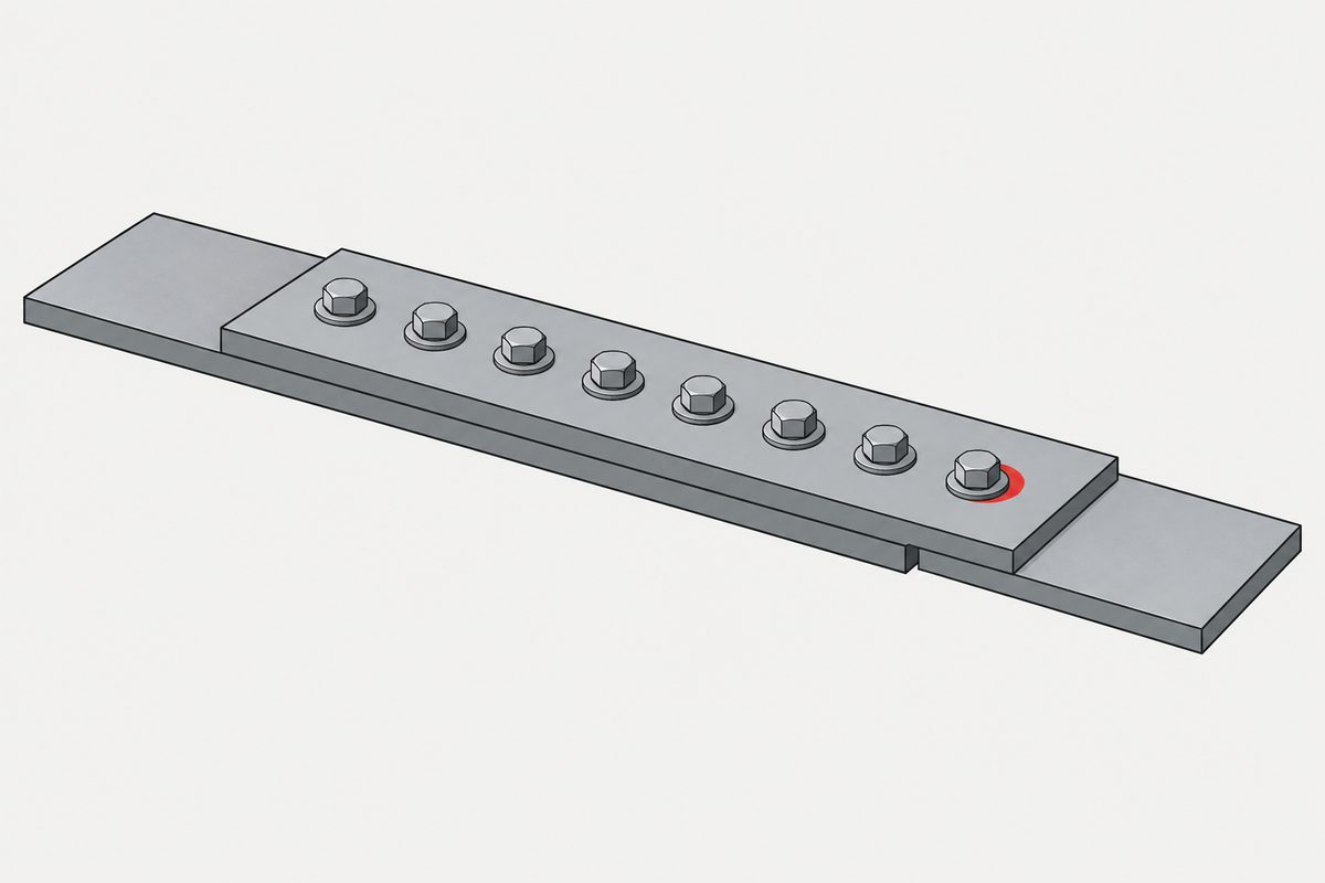
Why the outer bolts carry more
Take a splice: a main plate lapped by cover plates, load entering at the ends. Between any two adjacent bolt rows, the main plate and the splice plate stretch by different amounts, because they are carrying different fractions of the load at that station. That difference in elongation has to be taken up by the bolts, and it accumulates along the joint, so it is largest near where the load enters. The bolts nearest the ends therefore transfer the most shear, and the ones in the middle the least.
This applies to a specific case, not to bolts in general. The joint has to be end-loaded along the direction of the row, and the bolts have to be transferring shear by bearing against their holes. Before slip, a preloaded slip-critical joint transfers load by friction across the faying surfaces instead. And where load is introduced gradually along the length — a web-to-flange connection — both codes list it as an exception.
There is no ratio to quote
The obvious next question is how much more. There is no transferable answer: it depends on the number of bolts, the pitch and total length, the shear and bearing stiffnesses, the plate sections and how far they have yielded, hole clearance and the order in which bolts actually come into contact, and how far through the loading you are.
One thing to be careful about, because it is the natural mistake to make here: the code reduction factors are not the load ratio. They reduce the group strength. They do not tell you what any individual bolt is carrying.
Two codes, two different rules
Both codes reduce capacity for long end-loaded joints, and it is tempting to treat them as the same rule with different units. They are not.
| EN 1993-1-8 | AISC 360-22 | |
|---|---|---|
| Where | Cl. 3.8 Eq. (3.5) — 2024: Cl. 5.7.3 Eq. (5.7) | Table J3.2 footnote [c] |
| Threshold | 15d (diameter-normalised) | 38 in / 950 mm (absolute) |
| Form | continuous linear | single step |
| Factor | βLf = 1 − (Lj − 15d) / 200d, floor 0.75 | × 0.833 |
The EN factor runs 1.00 at 15d, 0.95 at 25d, 0.90 at 35d, and reaches its 0.75 floor at 65d. The AISC 0.833 has a derivation worth knowing, because it is not a 0.75 factor: the tabulated shear strength already includes a 0.90 length factor, and long end-loaded joints are meant to sit at 0.75, so the extra multiplier is 0.75 / 0.90 = 0.833. Applying 0.75 on top of the table would be double-counting.
So why is it ever legitimate to assume equal sharing?
Because the joint levels itself out as it is loaded, provided it can deform. The redistribution comes from several places at once: shear deformation of the bolts, local yielding and elongation of the holes in bearing, plastic deformation of the plates, and bolts that were not touching their holes progressively coming into bearing. As the end bolts soften, load moves inboard. In a short joint this can nearly equalise before any bolt fails; in a long one the end bolts may exhaust their deformation capacity first — the sequential end-inward failure that steel literature calls unbuttoning.
Unbuttoning is a real mechanism but not an inevitability: net-section rupture, block shear, end tear-out or slip can control the joint before it happens.
A caution against a plausible-sounding rule: it is not that the plate must not yield before the bolt. Local bearing yield in the plate is one of the main sources of the redistribution you are relying on. What must not happen is a failure mode with no deformation capacity — brittle net-section rupture, block shear or tear-out without ductility, thread stripping, brittle bolt fracture. EN 1993-1-8:2024 makes the condition explicit by requiring bolt shear resistance to reach at least 80% of bearing resistance before the ductile group assumption is used.
Tension and moment is a different calculation again
Where a moment tries to open the interface, the elastic model gives each bolt Fi = N/n + M·yi / Σyj2, with force varying with distance from the neutral axis. The trap is assuming the neutral axis sits at the bolt group centroid. It does so only for pure moment, a symmetric pattern, equal bolt stiffnesses, and a model that allows a linear reaction in both directions.
Real joints break those assumptions: bolts can pull but the interface can only push, so part of the face stays compressed while part separates, and the boundary has to be found by satisfying equilibrium — usually iteratively. A flexible end plate adds prying, which makes the linear distribution optimistic. And in-plane eccentric shear is not this problem at all: that one uses the centroid and polar moment, or the instantaneous-centre method.
Two things this is not, and one place it does not apply
It is not tightening sequence. Elastic interaction during assembly — tightening one bolt relaxing its neighbours through the flange or gasket — determines the scatter in initial clamp load. What this article describes is how additional service load is shared afterwards. The first sets the starting condition for the second, but they are different physical events and do not share a formula.
And it is not for small fasteners in products. EN 1993-1-8 is calibrated for structural steels and plate thicknesses generally from 3 mm; AISC 360 is for structural steel buildings. Neither is calibrated for a PCB, a plastic housing, a die-cast boss or a group of small self-tapping screws. What does carry across is the physics — relative stiffness governs sharing, clearance means the screws do not all bear at once, flexible plates distribute unevenly, local yielding enables redistribution. What does not carry across is 15d, 38 in, βLf, 0.833, and the ductility assumptions underneath them. For those joints the appropriate methods are NASA-STD-5020B or VDI 2230 style analyses, or test.
This is not one of the six steps. It shows up across them, or after assembly. Where the decisions that lead here were made is in specifying a screw, which sets out the order and why doing it out of order is rework.
Common questions
Do the end bolts always carry more?
Only in a joint loaded at its ends along the direction of the row, where the bolts are transferring shear by bearing in their holes. A preloaded slip-critical joint that has not slipped transfers load by friction across the faying surfaces instead, and a connection where load is introduced gradually along the length — a web-to-flange weld line, for example — is listed as an exception in both codes.
How much more does an end bolt carry?
There is no general figure, and the code reduction factors should not be read as one. Beta-Lf and the 0.833 multiplier reduce the strength of the group; they say nothing about what an individual bolt carries. The actual distribution depends on bolt count, pitch, joint length, bolt and plate stiffness, hole clearance, which bolts have come into bearing, and how far into the loading you are.
Are the EN and AISC long-joint rules the same?
No. EN 1993-1-8 starts reducing at a length of 15 diameters and falls linearly to a floor of 0.75 at 65 diameters, so it scales with bolt size. AISC 360-22 has no diameter-based threshold: it applies a single 0.833 multiplier to end-loaded connections longer than 38 inches. The 0.833 is 0.75 divided by the 0.90 length factor already built into the tabulated strength, so applying 0.75 directly would double-count.
Is this the same as tightening sequence?
No. Tightening sequence governs elastic interaction during assembly, where tightening one bolt changes the preload already in its neighbours through the flange or gasket, producing scatter in the initial clamp load. This article is about how additional load applied afterwards is shared between bolts. The first determines the starting condition for the second, but they are different events and use different analysis.
References
- Kulak, Fisher & Struik, Guide to Design Criteria for Bolted and Riveted Joints (§5.2.2 load partition and unbuttoning; Figs. 5.11–5.21)
- Fisher & Rumpf. Analysis of bolted butt joints. ASCE Journal of the Structural Division. DOI 10.1061/JSDEAG.0001328
- ANSI/AISC 360-22 — Table J3.2 footnote [c] and Commentary J3 (end-loaded connections over 38 in)
- NASA-STD-5020B — requirements covering load redistribution from clearance, local yielding, separation and slip
EN clause numbers differ by edition: the long-joint factor is Clause 3.8 Eq. (3.5) in EN 1993-1-8:2005 and Clause 5.7.3 Eq. (5.7) in the 2024 edition, which also expresses the reduction as applying to the joint resistance rather than to bolt shear resistance alone.
Enquiries
If the fasteners are in a group carrying shear, the count alone does not tell us what each one sees. Send the pattern and the load path, not just the quantity — particularly if the row is long or the load enters at one end.
Request a quotation
Tell us the part and the quantity. We will come back on feasibility, lead time and price.
Or email us directly sales@tigerfasteners.com