 TIGERFASTENERS
The Bolt Can See Twice the Load You Applied
A bracket is loaded to 10 kN and the bolt is rated well above it, and the bolt still fails. Nothing was overloaded in the sense anyone checked. The load that reached the bolt was simply not the load that was applied.
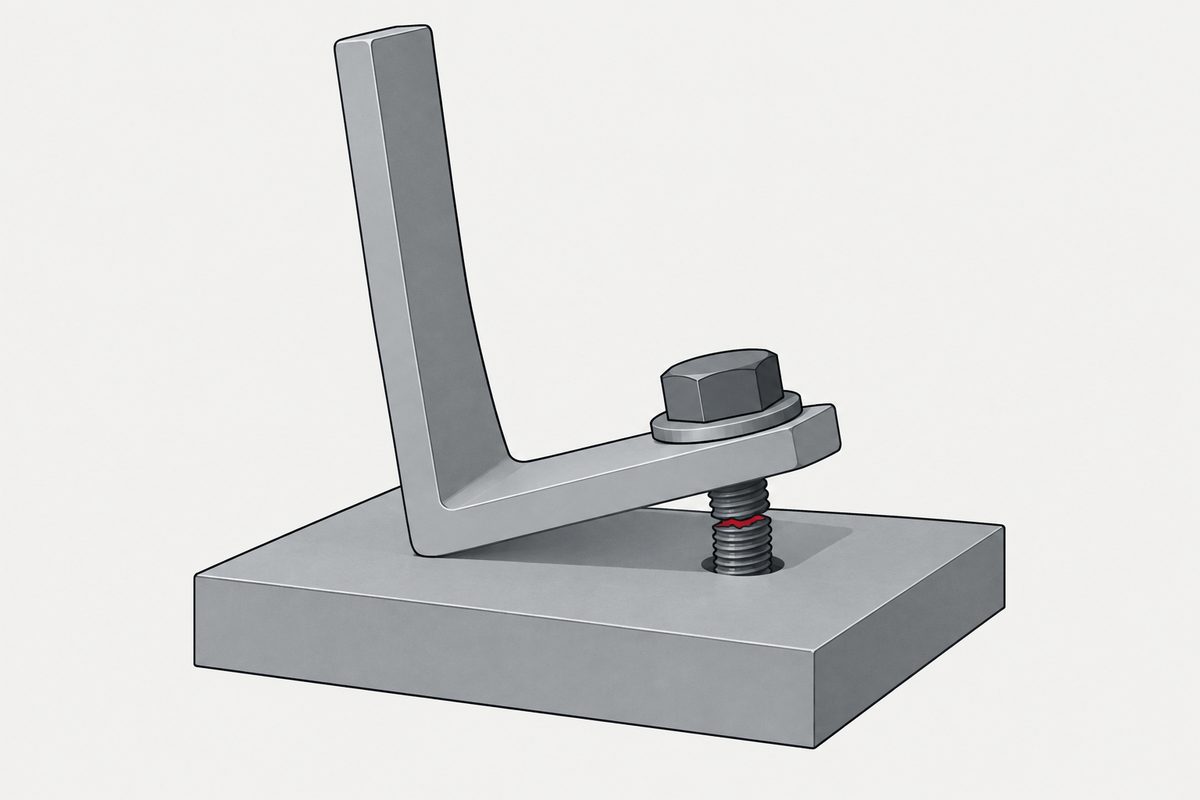
Where the extra force comes from
When a flange, angle leg or end plate is pulled and bends, the part of the interface outside the bolt line can stay in compression. That surviving contact pushes back. The bolt then has to equilibrate both the applied tension and that contact reaction:
B = T + Q — bolt tension equals applied tension per bolt plus the prying reaction.
The reason the interface can only push, never pull, is what makes this happen: as the region near the load lifts away, the compression that used to be spread out concentrates into whatever contact remains, and that concentrated reaction sits on a lever arm.
Two things that are commonly said and are not true
“Eccentric loading causes prying.” Not on its own. The member also has to bend while keeping contact outside the bolt line. A sufficiently rigid flange, or a geometry where the outer contact is lost, can produce negligible or zero prying. In the same test series that produced the doubling below, a specimen with a 32 mm flange, 20 mm bolts and the bolts 70 mm from the web centreline showed virtually no bolt-force increase before separation.
“The pivot is the edge of the flange.” The effective fulcrum is the remaining compressive contact region. It is idealised at the flange toe for calculation, but it moves with load, flange thickness, bolt-to-web distance and the stiffness of what is supporting it. Assuming it sits at the physical edge can be unconservative in an elastic analysis.
How large it gets, and what it does to fatigue
For opposing T-stubs contacting at their extremities, the measured prying force at separation was approximately equal to the applied load — Q/T ≈ 1.0, so the bolt saw about 2T. That is the doubling in the title, and it is a test result for that geometry, not a design factor to apply generally.
The fatigue consequence is the part worth remembering, because the applied load did not change between these cases:
| Static Q/T | Bolt stress range | Fatigue life |
|---|---|---|
| 0.02 | 2.2 ksi | > 3,000,000 cycles |
| 0.19 | 3.7 ksi | — |
| 0.45 | 10.4 ksi | 32,000 cycles |
All three under the same 0–25 kip applied load range per bolt. Geometry alone moved the life by roughly two orders of magnitude. Note also that prying amplifies the stress range, not just the mean stress — which is why it reaches fatigue at all, and why bolt bending can push the local range at the thread root higher still.
Tightening it harder is not the fix
This is the instinct, and the tests do not support it. Initial bolt clamping force was found not to materially affect the prying force at ultimate load. The prying reaction is a geometric consequence of bending and contact; preload does not remove the lever.
What preload does do is delay one-sided opening, which can keep a service cycle inside the linear low-slope regime where the bolt sees only its small share of the load. That is worth having, and it is the same thing preload buys in the ordinary tension joint — distance from separation, not a smaller share.
Prying can be designed out, though. AISC 358-22 defines a critical flange thickness required to eliminate prying action. Past that thickness, adding more does nothing further for prying. The counter-intuitive part: thickening only one flange can simply move the prying into the flexible flange supporting it, since the mechanism depends on relative stiffness.
Two traditions describe this, and they are not the same model
Steel-structure practice (AISC Manual Part 9, Design Guide 29) treats the T-stub as an ultimate-strength plastic mechanism, with lever arms, a critical thickness and a prying force. Machine-design practice (VDI 2230-1) treats a preloaded single bolt through compliances: before the opening limit the additional bolt load is a fixed fraction of the applied load, and after one-sided opening that linear relation is replaced by an opening construction.
They describe the same physical situation with different assumptions and are not interchangeable. One more caution on notation: classical literature writes the prying force as Q, while the current AISC Manual uses lowercase q for the actual prying force and reserves uppercase Q for a dimensionless strength multiplier. Reading a formula from one source into the other is a real way to get this wrong. The same split runs through how a group of bolts shares load, where the two codes disagree on the threshold as well as the factor.
Prying is also not simply “where the simple model breaks”. Contact can begin receding before the idealised opening threshold, so a constant load-factor model can already be optimistic while the joint still counts as closed — which the note on partial edge opening in the bolt is a spring also points at.
This is not one of the six steps. It shows up across them, or after assembly. Where the decisions that lead here were made is in specifying a screw, which sets out the order and why doing it out of order is rework.
Common questions
Does eccentric loading always mean prying?
No. Prying needs the member to bend while compressive contact survives outside the bolt line, so that the remaining contact can push back on a lever arm. A stiff enough flange, or a geometry that loses the outer contact, produces little or none. In the same test series that measured a doubling of bolt force elsewhere, a specimen with a 32 mm flange and bolts 70 mm from the web centreline showed virtually no bolt-force increase before separation.
Can I just use a higher preload to stop it?
Not to remove the prying force itself. Tests found initial clamping force did not materially affect prying at ultimate load, because the reaction comes from bending and unilateral contact rather than from how hard the bolt is pulled. Higher preload does delay one-sided opening, which can keep the working cycle in the linear regime where the bolt only takes its small share, so it helps the fatigue case without removing the mechanism.
How much extra load should I assume?
None as a default figure. The Q/T ratio of about 1.0 that doubles bolt tension belongs to opposing T-stubs contacting at their extremities; other specimens in the same work showed almost nothing. Prying depends on flange thickness, the bolt-to-web lever arm, the support stiffness and the contact geometry, which is why the design methods compute it rather than tabulate it.
Why does it matter so much for fatigue specifically?
Because it amplifies the stress range and not only the mean stress. In the reported tests, static Q/T values of 0.02, 0.19 and 0.45 gave first-cycle bolt stress ranges of 2.2, 3.7 and 10.4 ksi under an identical applied load range, and fatigue life fell from over three million cycles to about thirty-two thousand. Bolt bending can raise the local range at the thread root beyond the nominal axial figure as well.
References
- Kulak, Fisher & Struik, Guide to Design Criteria for Bolted and Riveted Joints, 2nd ed., ch. 17 (prying: §17.3–17.5, Figs. 17.6–17.10)
- Thornton, W. A. (1985). Prying Action — A General Treatment. AISC Engineering Journal
- VDI 2230 Part 1:2015-11 — Systematic calculation of highly stressed bolted joints (§5.3.2–5.3.3, load factor and opening limit)
The Q/T ratios, bolt stress ranges and fatigue lives are measured results from the specimens described in chapter 17 of the Guide and are specific to those geometries; no general prying factor exists. The critical flange thickness that eliminates prying is defined in ANSI/AISC 358-22 §13.5.
Enquiries
If the fastener is going into a bracket, angle or flange that can flex, tell us the geometry and not only the load. The bolt in that joint may be seeing considerably more than the number on the drawing, and that is a joint calculation rather than a fastener selection.
Request a quotation
Tell us the part and the quantity. We will come back on feasibility, lead time and price.
Or email us directly sales@tigerfasteners.com