 TIGERFASTENERS
An ordinary screw in a clearance hole cannot locate anything
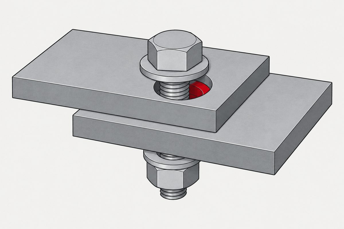
The short version: the hole is bigger than the screw on purpose. ISO 273 puts an M8 clearance hole at 9 mm in the medium series. That gap is not sloppiness — it is what lets the joint assemble and keeps the load path in tension and interface friction. Which means location has to be bought separately: from a pin, from a datum face, or from a different fastener whose unthreaded part was toleranced for the job.
The question, and the answer that is only half right
“Why can't screws be used for locating parts?” has been read nearly 4,000 times on Engineering Stack Exchange. The top-voted answer says screws are formed rather than ground, so they are nowhere near as accurate as a hardened, ground pin.
That is true, and it is not the reason. Grind an M8 screw to dowel-pin precision, put it through an ordinary 9 mm clearance hole, and you have gained nothing. The limiting interface is not the screw.
How big the hole is meant to be
ISO 273 specifies clearance holes for bolts and screws in three series. These are its numbers, not a shop convention:
| Thread | Fine | Medium | Coarse |
|---|---|---|---|
| M3 | 3.2 | 3.4 | 3.6 |
| M4 | 4.3 | 4.5 | 4.8 |
| M5 | 5.3 | 5.5 | 5.8 |
| M6 | 6.4 | 6.6 | 7.0 |
| M8 | 8.4 | 9.0 | 10.0 |
| M10 | 10.5 | 11.0 | 12.0 |
| M12 | 13.0 | 13.5 | 14.5 |
The standard also lists H12, H13 and H14 as the tolerance grades to use for fine, medium and coarse respectively — but explicitly as information, for use where specifying a tolerance is desirable. An ISO 273 hole does not automatically carry a positional requirement.
Two different quantities, and it is easy to run them together. Clearance is hole diameter minus shank diameter — nominally 1 mm on M8 medium, and it moves with the hole's diameter tolerance. Positional tolerance is where the hole's axis sits relative to the datums, which is a separate control and is established when the hole is drilled. Both affect where the part ends up. They are not the same number and one does not substitute for the other.
Why the gap is deliberate
A preloaded bolted joint is not meant to carry transverse load on the shank. It is meant to clamp the faces together hard enough that friction at the interface carries it, with the fastener in tension. The clearance is what makes that work: it lets the parts be drawn together without the shank picking up a bearing load on the way, and it absorbs the accumulated positional error of every hole in the pattern so the assembly goes together at all.
Remove the clearance and you have not improved the joint. You have changed what it is — now the shank can bear, and a fastener sized for tension is being asked to take shear it was not sized for.
What a pin buys, stated carefully
ISO 2338 parallel pins are supplied in m6 or h8. For a nominal 8 mm pin in m6, ISO 286 gives deviations of +6 µm to +15 µm — an actual diameter between 8.006 and 8.015 mm, a band of nine microns. The standard also calls for a surface finish below Ra 0.8 µm on m6 pins.
What that is not: it is not the fit. The fit depends on the hole you ream for it, and nobody can quote a fit without specifying both. What the nine microns tells you is that the pin has been manufactured to a different order of precision from anything in the clearance-hole table above — and that it is sold on the assumption you will ream a hole to match.
That is the actual difference. Not that a pin is accurate and a screw is not, but that a pin is a feature somebody paid tolerance for, on both the part and the hole. The clearance hole is a feature somebody deliberately did not.
All of that is about position. Once a pin is carrying load instead, a different document applies and the numbers stop matching people's expectations: a slotted spring pin has a published minimum double shear load and a hardened dowel pin has none at all. Only one of these two pins has a rated shear load works through both standards. And stopping a part rotating on a shaft is a third job again, where the standard for the obvious part never mentions the shaft. The reamed hole this page keeps recommending has its own gap: the dowel pin standards specify the pin and say nothing about the hole.
And a fastener can locate, if you buy that too
This is where the tidy version of the rule — “screws clamp, pins locate” — stops being true, and it is worth knowing because the counterexamples are catalogue parts.
- Fitted bolts (DIN 609 and DIN 610) have a toleranced unthreaded shank meant to sit in a reamed hole. They locate and they clamp.
- Shoulder screws (ISO 7379) have a ground shoulder with an f9 tolerance. The shoulder locates; the smaller thread below it clamps. Note the division of labour is inside one part — the thread still is not doing the locating.
⚠️ Shoulder screws are designated by the shoulder, not by the thread, and that is where orders go wrong. ISO 7379 - 10 × 40 means a 10 mm shoulder, 40 mm long — and the thread on that one is M8. The thread is always smaller than the shoulder, so “an M8 shoulder screw” has two readings: an M8 thread (shoulder 10) or an 8 mm shoulder (thread M6).
⚠️ Those pairings — 6.5 with M5, 10 with M8, 13 with M10 — are read from distributor catalogue sheets, not from the text of ISO 7379. Those are commercial documents. Check against the current standard before they go on a drawing. Give shoulder diameter, shoulder length and thread on the order and the ambiguity disappears.
Both cost more, and both require the hole to be reamed rather than drilled. Which is the same point again: the price of location is paid on the hole as much as on the fastener.
Why two pins and not three
When pins are the answer, the standard arrangement is one round pin and one diamond pin — DIN 6321 lists them as type B and type C.
On a part already sitting on a face, the round pin fixes position in the plane; the diamond pin fixes rotation about the round one. A third close-fitting pin usually constrains something already constrained, and now three centre distances have to agree simultaneously or the part will not go on. The flat on the diamond pin exists precisely to release the centre-distance direction so hole-spacing tolerance does not jam the assembly.
The formal versions of this idea are the 3-2-1 locating principle from fixture design and, more generally, exact-constraint (kinematic) design: constrain each degree of freedom you need, once. A third pin is not automatically wrong — if it floats, carries load rather than locating, or is there for poka-yoke, it is doing a different job.
Four ways to locate, none of them the thread
- Dowel pins — round plus diamond, reamed holes.
- A spigot or register — a machined diameter that centres one part on the other. Car wheels do this on hub-piloted designs; note that stud-piloted designs exist too, where conical or spherical nut seats do the centring instead.
- A fitted bolt or shoulder screw — as above, and it is the shank or shoulder doing the work.
- Datum faces, side stops, keys, tongues, V-blocks — positive geometry that the part is pushed against, with the screws only clamping. Often the cheapest of the four, and the one beginners skip.
What all four have in common is that the locating feature is not the threaded connection. Where thread and hole choices sit in the wider order of decisions is in specifying a screw; the related question of when to reach for something other than a screw entirely is in when not to use a screw.
A caution about the strong version of this
It is tempting to finish with “never let two features both locate”. That is over-stated. Ordinary preloaded joints resist transverse load through interface friction and do not need the shank to bear at all. Bearing-type connections and fitted-bolt joints are deliberately designed so the fastener does take shear. The genuine failure mode is narrower: several close-fitting features used as precision locators at once, with nothing absorbing the tolerance between them. That is what the flat on the diamond pin is for, and it is why the count is two.
References
- ISO 273 — Fasteners: clearance holes for bolts and screws (fine, medium and coarse series; H12/H13/H14 given for information)
- ISO 2338 — Parallel pins, unhardened (m6 and h8; Ra below 0.8 µm for m6)
- ISO 286 — ISO code system for tolerances (m6 on 8 mm: +6 to +15 µm)
- ISO 7379 — Hexagon socket head shoulder screws (shoulder tolerance f9)
- DIN 609 / DIN 610 — Fitted bolts with toleranced shank
- DIN 6321 — Locating pins, type B round and type C diamond
- 3-2-1 locating principle and exact-constraint design, fixture design literature
- “Why can't screws be used for locating parts?”, Engineering Stack Exchange
This page explains the reasoning behind a convention. Values for any particular part are governed by your drawing and the standards it invokes.
A key is the part you reach for when a fastener cannot hold position, and one standard for keys sizes them differently depending on whether they drive or only locate.
This page covers step 1, the substrate. The whole order is substrate, thread, head, drive, finish, documentation, and why doing it out of order is rework rather than a tweak is in specifying a screw.
Common questions
Why is the clearance hole bigger than the screw?
So the joint can be assembled and so the load path stays in tension. ISO 273 puts an M8 clearance hole at 9 mm in the medium series. That gap lets the parts be drawn together without the shank picking up a bearing load, and it absorbs the accumulated positional error of the hole pattern. Removing it does not improve the joint; it changes what the joint is.
Would a more accurate screw fix it?
No. Grind an M8 screw to dowel-pin precision, put it through an ordinary 9 mm clearance hole, and the roughly one millimetre of diametral clearance is still there. The limiting interface is the clearance hole and the shank, not the manufacturing precision of the screw. That is why the fix is a reamed hole, not a better screw.
So can a bolt ever locate a part?
Yes, if you buy a fastener made for it and ream the hole to suit. Fitted bolts to DIN 609 or DIN 610 have a toleranced unthreaded shank. Shoulder screws to ISO 7379 have a ground shoulder with an f9 tolerance that locates while the smaller thread below clamps. In both cases the locating feature is the shank or shoulder, never the thread.
Why one round pin and one diamond pin, rather than two round?
The round pin fixes position in the plane and the diamond pin fixes rotation about it. The flat on the diamond releases the centre-distance direction, so tolerance on the hole spacing does not prevent assembly. Two round pins would require both centre distances to agree exactly. DIN 6321 lists them as type B and type C.
Does tapping the hole make it less accurate?
It affects thread quality, not primarily the position of the hole. The hole position is established when the hole is drilled, before tapping. This matters because a common explanation for why screws cannot locate blames the tapping operation, when the more fundamental reason is simply that the clearance hole on the other part is deliberately oversized.
Enquiries
If a drawing has reached you calling for a fastener in a reamed hole, or a shoulder with a tolerance on it, that is a different part from an ordinary screw and it is worth confirming before quoting. Send the callout over and we will tell you which one it is.
Request a quotation
Tell us the part and the quantity. We will come back on feasibility, lead time and price.
Or email us directly sales@tigerfasteners.com