 TIGERFASTENERS
One Standard Sizes the Same Key Twice, Once for Driving and Once for Only Locating
A screw in a clearance hole cannot locate anything, which this site has written about before. A key is the other half of that thought: it is the part you reach for when a fastener cannot hold position. What is worth knowing is that the standard for one kind of key does not treat locating and driving as the same job. It gives two separate series of shaft diameter against key section, and the second one exists for keys that are not transmitting the torque at all.
From the clause on the relationship between shaft diameter and key dimensions: “la série 1 est relative au cas où la clavette transmet le couple et la série 2 au cas où la clavette sert à mettre l’arbre et le moyeu en position relative”, with the example given as torque transmitted from shaft to hub “non par l’intermédiaire de la clavette, mais par celui du frottement entre l’arbre et le moyeu ajustés avec serrage”.
The free preview of this standard is the French version, so every quotation on this page is the French text and every translation is ours. This page gives no design, selection or machining advice about keys, keyways or fits. It did not come from a forum question either; it comes from scanning fastener families for zero coverage, which is how the site found that it had never written the word keyway. The browser tooling we normally use remains unavailable.
A document from a different committee
The standard is ISO 3912, Woodruff keys and keyways, first edition dated 15 June 1977, priced on four pages. It was prepared by ISO/TC 14, shafts for machinery and accessories, and circulated to member bodies in October 1975. This is the first time this site has used it, and the first time it has used anything from that committee.
It is a scan of a 1977 document and the text extraction is unreliable on it, turning forme tronquée into nonsense among other things, so every quotation and figure here was read from a rendered page image.
The foreword records that three member bodies disapproved of the document on technical grounds. That is the third named dissent this site has come across, after one country objecting to the split pin hole standard; the contents of those pages are not repeated here.
Two jobs, stated in the first clause
The scope sets up the distinction before any table appears. The standard specifies the dimensional characteristics of the keys and of the corresponding keyways in the shaft and the hub, and it also gives the relationship between shaft diameter and key section, a relationship to be observed “tant dans le cas de transmission de couple que dans celui de simple positionnement”, both in the case of torque transmission and in that of simple positioning.
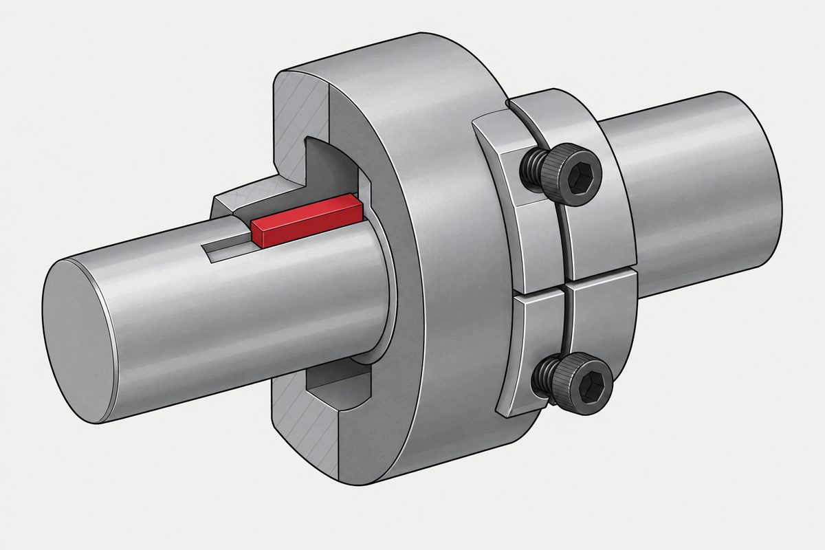
Those are named as two cases from the start, and clause 6 then supplies a separate series for each. Series 1 is for the key that transmits the torque. Series 2 is for the key that puts the shaft and hub in position relative to each other, and the standard gives the example that makes it concrete: the torque goes from shaft to hub not through the key but through the friction between shaft and hub fitted with interference.
So in series 2 the key is not the load path. The interference fit carries the torque, and the key is there to fix where the two parts sit relative to one another. It is doing the job that an ordinary screw in a clearance hole cannot do, and only that job.
We did not read the tables, so no key or keyway dimension appears on this page and we are not saying how the two series differ numerically. What the preview establishes is that they are two, and why.
The material clause promises to finish later
Clause 4 is three lines long and both of them are worth having. The material is steel of 590 newtons per square millimetre minimum tensile strength in the finished state, in the absence of a particular requirement agreed between the interested parties.
And then, as a note: “Les caractéristiques mécaniques de l’acier seront complétées ultérieurement.” The mechanical characteristics of the steel will be completed later.
That is a published International Standard carrying an explicit placeholder in its material clause. One tensile figure, a default that any agreement can override, and a written promise that the rest is still to come. Whether it ever came is not something this page can say: we did not check the current status of the document, because the catalogue page for it refuses us.
The scope carries a second unfinished reference. The standard applies to cylindrical shafts and shaft ends, and a footnote says that for tapered shaft ends the relationship between shaft diameter and key section is given in a standard described as in preparation, with no number filled in.
The designation does not name the form
The last clause is the one to take to a drawing. A key is designated by its width and its height and by reference to the standard, and two worked examples are given. For the ordinary form with a section of five by six and a half millimetres, the designation is Clavette ISO 3912 – 5 × 6,5. For the truncated form at five by five point two, it is Clavette ISO 3912 – 5 × 5,2.
Neither designation says which form it is. The words for ordinary and truncated appear in the standard, in the figures and in the explanation of the examples, but not in the code itself. The form is carried entirely by which height number is quoted, because one form uses the first height and the other uses the second.
That is our own observation rather than a statement by the standard, and it is the kind of thing worth noticing on any part specified by a short code: the code may be complete without being self explanatory. Someone reading five by five point two has to know that the second number is a different height on a different form, and nothing in the string tells them.
What this settles and what it does not
- The standard names two cases in its scope, torque transmission and simple positioning, and supplies a separate shaft diameter to key section series for each
- Series 2 exists for keys that do not transmit the torque, with the example that the torque passes through friction between shaft and hub fitted with interference
- The material is steel of 590 newtons per square millimetre minimum tensile strength in the finished state, unless the parties agree otherwise
- A note says the mechanical characteristics of the steel will be completed later, in a published standard
- A footnote points at a standard for tapered shaft ends that is described as in preparation, with no number
- The designation gives width and height only, and by our reading the form is implied by which height is quoted rather than named
- Three member bodies disapproved on technical grounds, and the preview does not say why
- The free preview is the French version, so all quotations are French and all translations are ours
- The tables were not read, so no key or keyway dimension appears here, and we did not check whether the document is still current
- No design, selection or machining advice is given
The useful part is the distinction, not the dimensions. A part can be sized differently depending on whether it carries the load or merely fixes a position, and a standard that takes that seriously will say so before it prints a table. It is worth asking of anything in a joint: is this holding the load, or is it deciding where things are? The answer changes what the part has to be.
This is not one of the six steps. It shows up across them, or after assembly. Where the decisions that lead here were made is in specifying a screw, which sets out the order and why doing it out of order is rework.
Common questions
Does a key always transmit the torque?
Not in this standard. It gives two series of shaft diameter against key section: series 1 for the case where the key transmits the torque, and series 2 for the case where the key puts the shaft and hub in position relative to each other, with the example that the torque passes from shaft to hub through friction between them where they are fitted with interference.
What is the difference between the two series numerically?
This page does not say. The tables were not read, so no key or keyway dimension appears here. What the preview establishes is that there are two series and what each is for.
What material does it specify?
Steel of 590 newtons per square millimetre minimum tensile strength in the finished state, in the absence of a particular requirement agreed between the interested parties.
Does it give full mechanical properties?
No. A note in the material clause states that the mechanical characteristics of the steel will be completed later. That is a placeholder inside a published International Standard, and this page does not say whether it was ever filled in.
How is a key designated?
By its width and its height and by reference to the standard. The two worked examples are five by six and a half for the ordinary form and five by five point two for the truncated form.
Does the designation say which form the key is?
By our reading, no. The words for the two forms do not appear in the code. The form is carried by which height number is quoted, since one form uses the first height and the other the second.
Which committee wrote it?
The committee for shafts for machinery and accessories, not the fastener committee. It is a first edition dated 15 June 1977, circulated to member bodies in October 1975.
Did everyone agree with it?
No. The foreword records that three member bodies disapproved of the document on technical grounds. The preview does not say what the objection was.
Is this standard still current?
This page does not say. We did not check, because the catalogue page for the document refuses requests from this site.
References
Every quotation and figure on this page was read from rendered page images, because this is a scan of a 1977 document and the text extraction is unreliable on it. The free preview is the French version of the standard, so all quotations are the French text and all translations into English are ours; that is stated in the body rather than glossed. This is the first time this site has used this standard, and the first time it has used a document from that technical committee. The tables were not read, so no key or keyway dimension appears here and nothing is said about how the two series differ numerically. We did not check whether the document is current or has been superseded, because the catalogue page refuses requests from this site; that gap is stated rather than filled. The following is our own observation, not a statement by the standard: that the designation carries the form only through which height is quoted, since the words for the two forms do not appear in the code. The three member bodies that disapproved on technical grounds are recorded in the foreword, which does not say why, and the earlier pages on other standards with named dissents are linked rather than repeated. This article did not come from a forum question; it comes from scanning fastener families for zero coverage, the same list that produced two earlier pages. No design, selection or machining advice is given about keys, keyways or fits, and no brand is named. The browser tooling this site normally uses remains unavailable.
Enquiries
If a part on your drawing is there to hold a position rather than to carry the load, that is worth writing down, because the two duties can size the same part differently. Tell us which job it is doing and we will tell you which properties we can evidence for it.
Request a quotation
Tell us the part and the quantity. We will come back on feasibility, lead time and price.
Or email us directly sales@tigerfasteners.com