 TIGERFASTENERS
The Standard for Split Pin Holes Does Not Say Where the Hole Goes
A castle nut with a torque specification of 27,0 plus or minus 2,5 newton metres, and a cross hole in the stud that may or may not line up with a slot when you get there. That problem has two halves and this site has already written about one of them. The other half is the hole, and there is an International Standard for it. It gives the diameter, a minimum distance from the end and a position tolerance, and then says the position must be worked out for each application.
The note printed under the table of split pin hole dimensions: “The value for lh must be calculated for each application, but the hole should not be nearer the end of the fastener than le min. after taking into account the cumulative tolerances on lh and l.”
This page gives no advice about tightening a castle nut. The question that led here has a practical answer and we have already written it down from an aircraft maintenance document, on a page about safetying, which states plainly that you never torque a bolt to make the holes line up. The nut end of the problem is covered too, on a page about castellated nuts. Neither of them looked at the hole itself, and that is all this page is about. The question came from a public mechanics question site through its open interface, the browser tooling this site normally uses being unavailable again. We read the question and not its answers, and no username appears here.
A three page standard for two holes
ISO 7378:1983 is titled Fasteners, Bolts, screws and studs, Split pin holes and wire holes. First edition, 1 February 1983, prepared by ISO/TC 2 and circulated to member bodies in December 1981. It is priced on three pages, and its scope says it lays down the dimensions and position of those holes, applying unless “otherwise specified in the appropriate product Standard.”
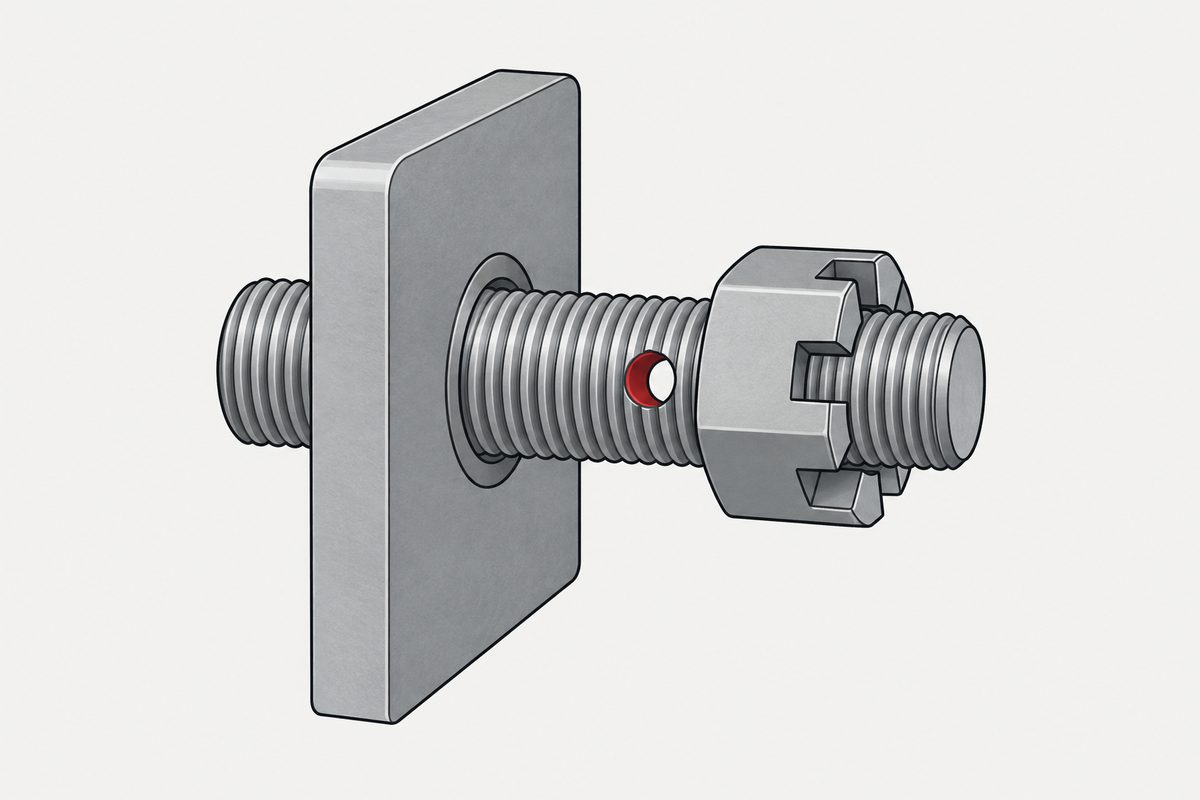
Two features are covered and they are not the same feature. The drawings show the split pin hole through the shank near the threaded end, dimensioned from the length of the fastener, and the wire hole through the head, dimensioned from the head height. One is for a pin that goes through a nut slot; the other is for wire.
The foreword carries something worth recording, because it is a fingerprint on a document that otherwise reads as pure geometry. The member body of the United States expressed disapproval of the document on technical grounds. The standard was published anyway. We do not know what the objection was and the preview does not say.
What it does give you
For split pin holes the table runs from a thread diameter of 4 mm up to 52 mm and supplies two numbers per size: the hole diameter to H14, and a minimum end distance. Reading the first half of it:
- M4 hole 1 mm, minimum end distance 2,3 mm
- M6 hole 1,6 mm, 3,3 mm
- M8 hole 2 mm, 3,9 mm
- M10 hole 2,5 mm, 4,9 mm
- M12 hole 3,2 mm, 5,9 mm
- M16 hole 4 mm, 7 mm
- M20 hole 4 mm, 7,7 mm
Two things fall out of that once you divide. By our arithmetic the minimum end distance drops from about 0,58 of the thread diameter at M4 to about 0,39 at M20, and not smoothly: M6 sits higher than M5, and M18 and M20 share the same 7,7 mm, which is where the ratio falls hardest. The edge distance is not proportional to the size, and a rule of thumb built at one diameter will not survive being carried to another.
Eleven sizes from M4 to M20 share only seven distinct hole diameters. M6 and M7 both take 1,6 mm, M12 and M14 both take 3,2 mm, and M16, M18 and M20 all take 4 mm. The hole is standing still while the bolt grows.
The wire hole table is separate and does not agree with the split pin table. At M12 the split pin hole is 3,2 mm and the wire hole is 2 mm; at M20 they are 4 mm and 3 mm. Two holes, one standard, different sizes for the same thread, because they are for different things.
The position, and the tolerance on it
Now the part the title of this page is about. Both tables carry the same tolerance block for the position of the hole, given by product grade: grade A is 2 IT 13, grade B is 2 IT 14, grade C is 2 IT 15, referred to the general tolerance standard for fasteners.
We are not converting those into millimetres. The tolerance standard they refer to was not read for this page, and neither was the underlying system of IT grades, so a figure here would be arithmetic performed on documents we have not opened. What can be said without opening them is the shape of it: the tolerance is expressed as two of an IT grade, and the three grades are consecutive, so the permitted wander grows step by step from product grade A to grade C.
What a product grade does and does not promise is a separate page here. The relevant point is that the same letter that controls the head and the shank is also controlling where this hole lands.
And then the note. The distance from the bearing face to the hole, must be calculated for each application. The standard bounds the hole from the far end, by requiring that it sits no nearer the end of the fastener than the minimum end distance once the cumulative tolerances have been taken into account, and it offers a production observation: a tolerance of plus IT14 on that length is generally practicable. What it does not do is place the hole.
Why that matters to the person under the car
Because it explains the shape of their problem rather than solving it. They have a nut that can only stop where a slot meets a hole, a torque range of five newton metres wide, and a hole whose position is not fixed by the fastener standard at all. It is set by whoever drew the part, within a band, and the band widens with the product grade.
So the alignment is not a property of the fastener system. It is a property of one drawing, and two parts made to the same standard, in different grades, will not present the slot and the hole to each other in the same place. The document that governs the hole says so twice over: once by handing the length back to the application, and once by putting a tolerance on it.
The practical rule stays where it was, in the maintenance document rather than in the dimensional one. That document has already been quoted here, and this page adds nothing to it. What this page adds is why the rule has to exist: nobody standardised the thing that would have made the problem go away.
What this settles and what it does not
- There is an International Standard for split pin holes and wire holes in bolts, screws and studs, three pages, first published in 1983
- It gives hole diameter and a minimum end distance for thread diameters from 4 mm to 52 mm, and a position tolerance by product grade
- It does not give the position of the hole along the fastener, which the note says must be calculated for each application
- The minimum end distance is not proportional to size, falling from about 0,58 d to about 0,39 d between M4 and M20 by our arithmetic, and not smoothly
- Eleven sizes share seven hole diameters in the range we read
- The split pin hole and the wire hole are different sizes at the same thread, 3,2 against 2 at M12 and 4 against 3 at M20
- The United States voted against the document on technical grounds, and the preview does not say why
- No millimetre value is given here for the position tolerance, because the tolerance standard it refers to was not read
- This page gives no tightening advice, and the practical rule about not torquing to align holes belongs to a different document we have covered separately
The useful residue is small and worth having. When a feature has to line up with something, check whether any standard actually locates it. Here the answer is that the diameter is standardised, the edge distance is standardised, the permitted error is standardised, and the location is left to the drawing.
A later page found a standard where three member bodies disapproved on technical grounds rather than one.
This page covers step 6, the documentation. The whole order is substrate, thread, head, drive, finish, documentation, and why doing it out of order is rework rather than a tweak is in specifying a screw.
Common questions
Is there a standard for the cotter pin hole in a bolt?
Yes. ISO 7378:1983, Fasteners, Bolts, screws and studs, Split pin holes and wire holes, first edition 1 February 1983, prepared by ISO/TC 2. It is priced on three pages and covers thread diameters from 4 mm to 52 mm.
Does it say where along the bolt the hole goes?
No. A note under the table states that the value for the distance to the hole must be calculated for each application. The standard requires only that the hole sits no nearer the end of the fastener than a tabulated minimum, once the cumulative tolerances have been taken into account, and observes that a tolerance of plus IT14 on that length is generally practicable in production.
What size is the hole?
It depends on the thread and on which hole. For split pin holes, 1 mm at M4, 1,6 mm at M6, 2 mm at M8, 2,5 mm at M10, 3,2 mm at M12, and 4 mm at M16 through M20, all to H14. Wire holes are tabulated separately and are smaller at the larger sizes: 2 mm at M12 and 3 mm at M20.
What is the tolerance on the hole position?
It is given by product grade: two IT 13 for grade A, two IT 14 for grade B and two IT 15 for grade C, referred to the general tolerance standard for fasteners. This page gives no millimetre equivalent, because that tolerance standard was not read.
Is the minimum end distance a fixed fraction of the diameter?
No. By our arithmetic it falls from about 0,58 of the thread diameter at M4 to about 0,39 at M20, and it does not fall smoothly. M18 and M20 share the same minimum of 7,7 mm, which is where the ratio drops most.
Are the split pin hole and the wire hole the same?
Not the same feature and not the same size. The drawings show the split pin hole through the shank near the threaded end and the wire hole through the head. At M12 the split pin hole is 3,2 mm and the wire hole is 2 mm.
So how do I get the slot to line up with the hole?
This page does not answer that. The practical rule comes from an aircraft maintenance document and this site has covered it separately: you do not torque a bolt to make holes line up.
Did everyone agree on this standard?
No. The foreword records that the member body of the United States expressed disapproval of the document on technical grounds. The preview does not say what the objection was.
References
- ISO 7378:1983, Fasteners, Bolts, screws and studs, Split pin holes and wire holes, first edition, 1 February 1983. Free preview, eight pages, covering the foreword, scope, reference, and both dimension clauses with their tables
- The question that led here, on a public mechanics question site. Eleven votes, five answers
The preview was downloaded complete and both dimension tables were read from rendered page images. That was not optional here: text extraction misread this document badly, turning 3,9 into 33, 4,9 into 43 and 6,5 into 63, so every figure quoted on this page comes from an image. This is the first time this site has used ISO 7378. Only the first half of the split pin hole table, from M4 to M20, was read from an image, and no individual value from M22 to M52 is quoted here; the range is taken from the table headings. The following are our own arithmetic, not statements by the standard: that the minimum end distance falls from about 0,58 of the thread diameter to about 0,39 between M4 and M20 and does not fall smoothly; that eleven sizes in that range share seven distinct hole diameters; and the comparison between the split pin hole and the wire hole at M12 and M20. The tolerance standard the position tolerance refers to was not read, nor was the underlying system of IT grades, so no millimetre equivalent for two IT 13, two IT 14 or two IT 15 appears anywhere on this page. This page gives no tightening or assembly advice and does not diagnose any vehicle. The practical rule about hole alignment belongs to an aircraft maintenance document covered on a separate page here, and the nut end of the problem is covered on another; neither is repeated. No brand is named. The question came from a public mechanics question site rather than the forum tooling this site normally uses, which remains unavailable. We read the question and not its answers, and no username appears here.
Enquiries
If a drawing calls for a cross hole and gives it only a diameter, the position is the part that will cost you later, because the standard behind it hands that back to the drawing. Send the detail as written and we will tell you what we can hold and what has to be dimensioned before anyone can quote it properly.
Request a quotation
Tell us the part and the quantity. We will come back on feasibility, lead time and price.
Or email us directly sales@tigerfasteners.com