 TIGERFASTENERS
One hole, three shafts, three different joints
The short version: in almost every fit you will meet, the hole is the fixed one and the shaft is the variable. Look at any fits table and the left-hand column is H over and over. That is the system telling you something about how it expects parts to be made — and it gives you a rule for the cases where the assumption does not hold.
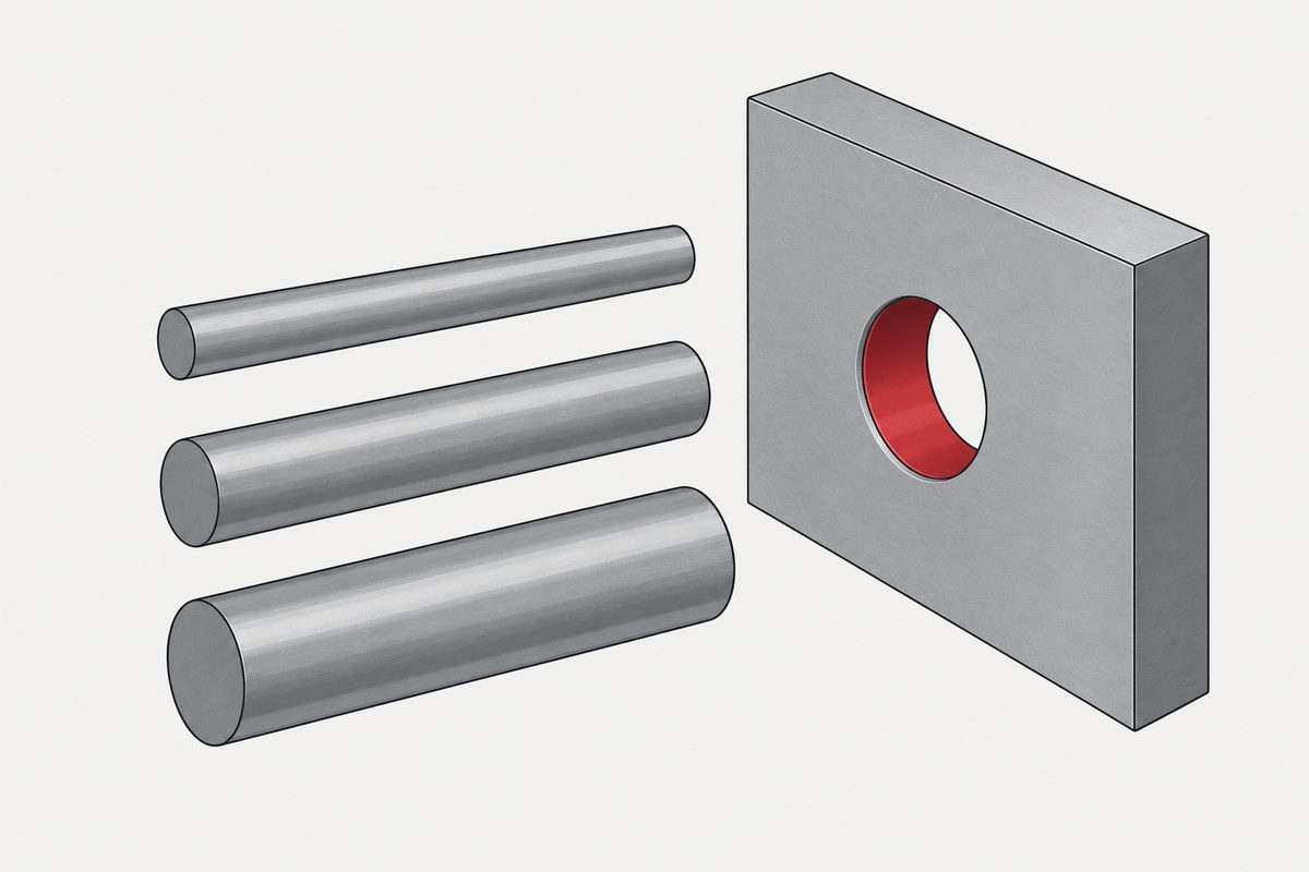
Same hole, three shafts
Take a nominal 8 mm feature. In the ISO 286 size step “over 6 up to and including 10 mm”, an H7 hole runs from +15 to 0 µm — that is, 8.000 to 8.015 mm. Now put three standard shafts into it and read what happens:
| Class | Upper | Lower | Against H7 |
|---|---|---|---|
| H7 (hole) | +15 | 0 | — |
| g6 | −5 | −14 | clearance 5 to 29 |
| k6 | +10 | +1 | interference up to 10, or clearance up to 14 |
| p6 | +24 | +15 | interference 0 to 24 |
| h6 | 0 | −9 | clearance 0 to 24 |
Those three lines are the three families. g6 is always loose. p6 is never loose. k6 could be either, and which one you get depends on where in tolerance the two parts happen to land — that is what a transition fit is, not a compromise but a genuine coin toss inside a bounded range.
One number in that table deserves a second look: the minimum interference of H7/p6 is zero. A hole at its smallest is 8.000 and a p6 shaft at its smallest is 8.015, so you get 15 µm — but a hole at its largest is 8.015 and meets a shaft at 8.015 exactly. An interference fit specified this way can, at the limits, deliver no interference at all. If the joint depends on grip, that is the case to design against.
Now notice what did not change
Three completely different joints, and the hole was H7 in all three. That is not an accident of the example. Open any fits table and the same thing happens: H7, H8, H9 down the left, and the variety comes from the shaft letters.
ISO 286 does define both arrangements. In a hole-basis system the hole is H — lower deviation zero, so it never goes under nominal — and the shaft letter creates the fit. In a shaft-basis system the shaft is h — upper deviation zero — and the hole letter does the work. Uppercase letters are holes, lowercase are shafts, throughout.
So both exist, and one of them is what you will actually meet.
The explanation usually given, and what we could not check
The reason repeated in workshops and textbooks is about tooling. Holes come out of tools that are themselves a fixed size — a drill, a reamer, a broach. Shafts come off a lathe or a grinder at whatever size you dial in. So if you standardise the hole at H and vary the shaft, you need one reamer per nominal size. Do it the other way round and you need a different reamer for every fit.
We could not verify that this is what ISO 286 says. The standard defines both systems and their notation; we did not find a clause stating a preference or giving this rationale, and we did not find an authoritative source attributing it to the standard. So treat it as the explanation that is widely given, which is not the same as the explanation the standard gives.
It also has an obvious modern objection worth stating: on a CNC machine a bore can be interpolated to any size, which weakens the tooling argument for anything milled or bored rather than drilled and reamed.
The rule that does not depend on settling that
Whatever the historical reason, the working question is not “which fit should I use”. It is:
Which of these two surfaces can I not change?
Fix that one, vary the other. Most of the time you are making both parts and the hole is the awkward one, so the hole is fixed at H and you choose a shaft letter. That is hole basis, and it is the default because the assumption usually holds.
When the assumption does not hold, the answer flips. If the shaft is bought rather than made — a rolling-element bearing inner ring, a length of cold-drawn bar, a standard spindle — then its diameter arrived with the part and the thing you can still choose is the hole. That is shaft basis, and it is not an exotic case; it is what you are doing every time you bore a housing to suit a bearing.
Where this connects to fasteners
The same question runs underneath why an ordinary screw in a clearance hole cannot locate anything: a dowel pin is a feature somebody paid tolerance for on both sides, and a clearance hole is one where somebody deliberately did not. Reaming a hole to suit a pin is exactly the exercise above — and the pin, being bought to m6 or h8, is the surface you cannot change. Which raises the question of who specifies the other one, and the answer is nobody: the dowel pin standard has no hole in it.
For what happens when no tolerance is stated at all, see the general-tolerance note in the title block. Where dimensional choices sit in the wider order is in specifying a screw.
References
- ISO 286-1:2010 — ISO code system for tolerances: bases, notation, and the classification of clearance, transition and interference fits
- ISO 286-2:2010 — tables of standard tolerance classes and limit deviations (values above from the “over 6 up to and including 10 mm” step)
- “How do you apply fits and tolerances when designing hole and shaft?”, Engineering Stack Exchange
This page explains how the system is organised. Values for any particular part are governed by your drawing and the standards it invokes.
This page covers step 2, the thread. The whole order is substrate, thread, head, drive, finish, documentation, and why doing it out of order is rework rather than a tweak is in specifying a screw.
Common questions
What are the deviations for H7, g6, k6 and p6 at 8 mm?
In the ISO 286-2 step over 6 up to and including 10 mm, all in micrometres: H7 hole is plus 15 to 0; g6 shaft is minus 5 to minus 14; k6 shaft is plus 10 to plus 1; p6 shaft is plus 24 to plus 15; h6 shaft is 0 to minus 9. Against the H7 hole that gives clearance of 5 to 29 for g6, either interference up to 10 or clearance up to 14 for k6, and interference of 0 to 24 for p6.
What is a transition fit, exactly?
One where the tolerance zones overlap, so the assembled result can be either a clearance or an interference depending on where the two parts land within tolerance. It is not a compromise between the two; it is a bounded uncertainty. H7/k6 at 8 mm can give up to 10 micrometres of interference or up to 14 micrometres of clearance.
Why is the hole always H in fits tables?
Because those tables are hole basis: the hole is fixed at H, whose lower deviation is zero, and the shaft letter creates the fit. ISO 286 defines shaft basis too, where the shaft is h and the hole letter varies. The explanation usually given for the preference is tooling — holes come from fixed-size tools while shafts are turned to any size — but we could not verify that ISO 286 itself states this, so treat it as the common explanation rather than the standard one.
When should I use shaft basis instead?
When the shaft is bought rather than made, so its diameter arrived with the part and the hole is the only surface left to choose. Rolling-element bearing inner rings, cold-drawn bar and standard spindles are the everyday cases. Boring a housing to suit a bearing is shaft basis whether or not anyone calls it that.
Can an interference fit end up with no interference?
At the limits, yes. H7/p6 at 8 mm has a minimum interference of zero: a hole at its largest, 8.015, meets a p6 shaft at its smallest, also 8.015. If the joint relies on grip rather than on location, that limiting case is the one to design against.
Enquiries
Most fastener work never needs this system — clearance holes are not fits. Where it does come in is dowelled and reamed features next to the screws. If a drawing has both and you are unsure which surface is the fixed one, send it over.
Request a quotation
Tell us the part and the quantity. We will come back on feasibility, lead time and price.
Or email us directly sales@tigerfasteners.com