 TIGERFASTENERS
Thread-forming screws into metal: the hole is the variable
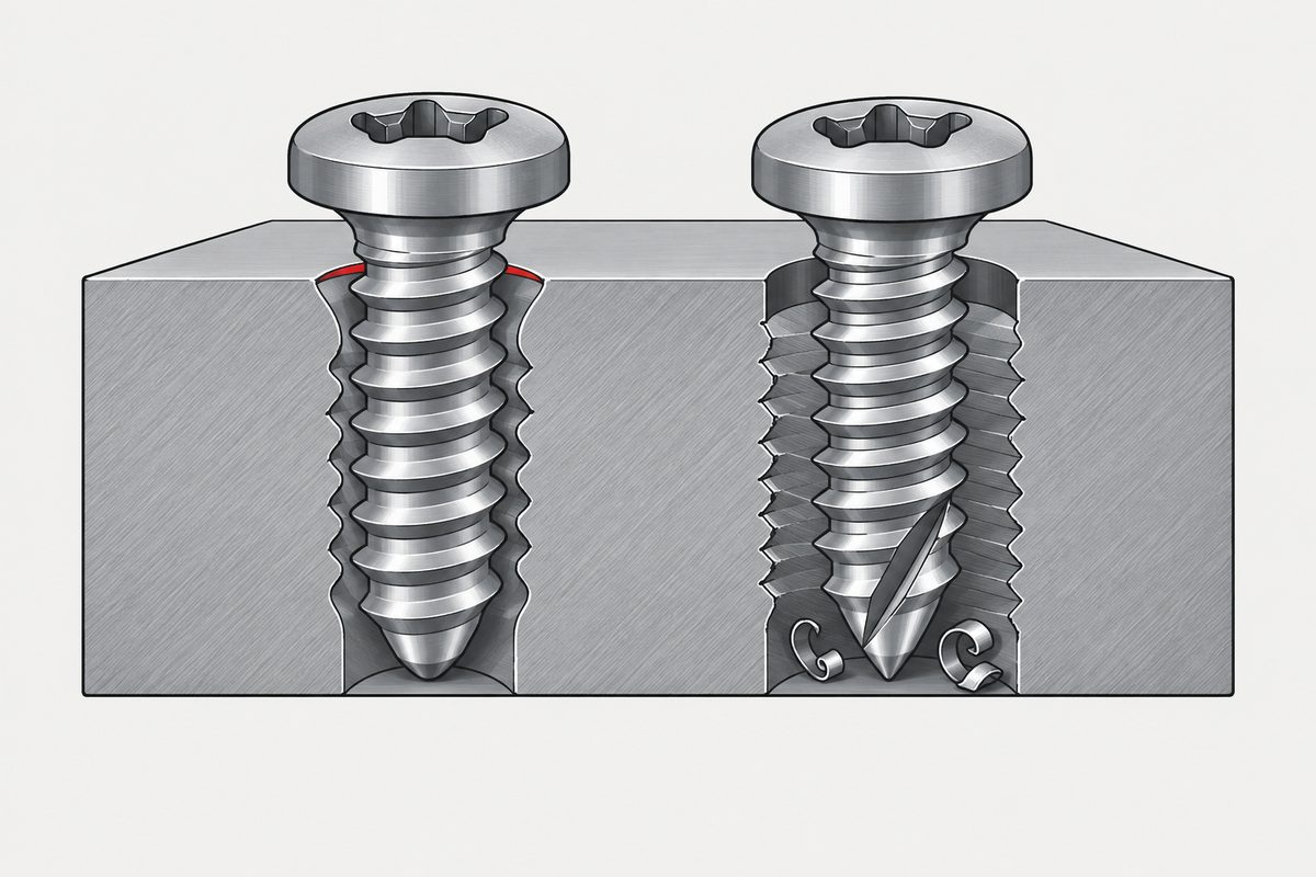
A thread-forming screw makes its own mating thread by pushing the parent metal out of the way. A thread-cutting screw makes one by removing material. The difference that matters on a drawing is not the screw: it is how tightly the hole has to be held. In the two DIN documents that cover these directly, the forming hole gets about 60% of the tolerance width the tapping screw is allowed.
The standards situation is messier than you would expect
This is worth getting straight first, because it is easy to cite something that no longer exists.
| Document | Status and scope |
|---|---|
| DIN 7500-1:2021-07 | Current. Technical specifications for case hardened and tempered thread-forming screws, M2 to M12 |
| DIN 7500-2:2016-04 | Current. Guideline values for hole diameters |
| ISO 7085:1999 | Withdrawn 2010-02-10. There is no current ISO equivalent |
| ISO 1478:1999 | Current, but narrower than its name suggests — thread and point dimensions for ST1.5 to ST9.5 tapping screws only |
| DIN 7513 / DIN 7516 | Thread-cutting screws with ISO metric threads |
The withdrawal is the part people miss. The European version of ISO 7085 was withdrawn over technical problems with its breaking torque and hardness requirements, and DIN 7500-1 took over. So a drawing that calls up “ISO 7085” is calling up nothing.
One more correction while we are here, because we had it wrong ourselves. DIN 7500-1 does not specify a trilobular cross-section. It is a performance and technical-conditions standard; the screw profile is the manufacturer's. Trilobular is the dominant implementation in the market, not the thing the standard requires.
What the lobes actually do
The usual explanation — and the one we drafted — is that a trilobular screw touches the hole at three points, so forming happens intermittently and the material relaxes in between. That is not quite what happens.
As the screw turns, the lobes sweep continuously along the hole wall. There are not three fixed points, and the forming action does not stop. What the lobed form does is:
- reduce the area in contact at any one moment, compared with a fully round section;
- concentrate the plastic forming pressure on the lobes;
- lower friction and therefore the forming torque;
- push displaced material toward the smaller-diameter relief zones, with elastic-plastic recovery once a lobe has passed.
Finite-element work confirms the lower driving torque and attributes it to the smaller contact area. There is no general percentage to quote, so if a supplier gives you one, ask what hole, material and thickness it came from.
What happens on the parent side
Two things here are well supported, and one is often overstated.
| Claim | How well it holds |
|---|---|
| Forming produces no chips; cutting does | Supported. Forming builds the thread by plastic flow; cutting removes material with an edge |
| The formed zone shows plastic deformation, elongated grains and local work hardening | Supported by microhardness studies |
| Grain flow is continuous rather than cut through | Reasonable as a metallurgical description, but not every metal, hole size and crest produces a complete uninterrupted flow line |
| Therefore pullout and stripping strength are higher | Not established. See below |
Three numbers people quote that we could not stand behind
We went looking for these specifically, because they are the ones that turn up in supplier literature and get copied into specifications.
- “Stripping torque should be at least 3:1 against driving torque.” We could not find this as a standard requirement. The performance tables in DIN 7500-1 and the withdrawn ISO 7085 compare maximum driving torque with the screw's own minimum breaking torque — not the parent material's stripping torque. The 3:1 figure does appear in vendor test data for specific thin steel sheet, where measured ratios ran about 2.0:1 to 3.4:1. That is product, hole and thickness specific.
- “Thread-forming gives higher pullout strength than thread-cutting.” Not established between the two screw types. The solid comparative studies are between form taps and cut taps. One reports roughly 27% higher tensile strength for formed threads in C22 steel, which cannot simply be transferred to a comparison of two screws.
- “Forming has no cutting allowance.” We wrote this ourselves and removed it. It is not a standardised statement and it implies a precision the documents do not support.
The hole, which is where the real difference shows up
Here there is something concrete. Compare the hole tolerance the two DIN documents recommend:
| Nominal | H11 (forming, DIN 7500-2) | H12 (ST tapping, DIN 7975) |
|---|---|---|
| over 1 to 3 mm | 0.060 mm | 0.100 mm |
| over 3 to 6 mm | 0.075 mm | 0.120 mm |
| over 6 to 10 mm | 0.090 mm | 0.150 mm |
The forming hole gets roughly 60% to 62.5% of the width. That is the practical consequence: the same drilling process that was comfortable for a tapping screw may not hold the window a forming screw needs.
Hole diameter is also, on the evidence, one of the most important variables in the process. Open it up and forming torque falls, but so does thread fill and the margin against stripping. Close it down and you displace more material and the forming torque rises.
But the hole is not the whole specification, and the standard says so. DIN 7500-2 gives its diameters as guideline values, derived from manufacturer and user trials, and explicitly requires you to validate before mass production. It notes that the screw's forming-zone geometry, the parent material, the effective engagement length, how the hole was made, and work hardening at the hole wall all change the diameter you need. Punched holes, cast skin and non-round holes can all need something different. The 2016 edition covers steel and aluminium; copper data was removed.
What to settle before it goes on the drawing
- Which mechanism the joint needs — chips are a contamination question as much as a strength one, and that is covered in choosing a screw type.
- The hole diameter and its tolerance, not just the diameter. H11 is a recommendation, not a result you get for free from an existing drilling process.
- How the hole is produced. Punched and drilled holes of the same nominal size do not behave the same.
- Whether the joint comes apart in service. A thread made on the way in is a different proposition on reassembly — see reusing a screw.
- Validation before volume, because the standard asks for it explicitly.
For the plastics case, which behaves differently enough to need its own treatment, see screws for plastic. Where this decision sits among the others is in specifying a screw.
References
- DIN 7500-1:2021-07 — thread forming screws for ISO metric thread, technical specifications for case hardened and tempered screws, M2 to M12
- DIN 7500-2:2016-04 — guideline values for hole diameters; H11 recommendation; validation requirement
- ISO 7085:1999 — withdrawn 2010-02-10, no current ISO equivalent
- ISO 1478:1999 — tapping screws thread, ST1.5 to ST9.5 thread and point dimensions
- DIN 7975:2016-04 — hole data for ST tapping screws in metal, H12
- DIN 7513 / DIN 7516 — thread-cutting screws with ISO metric threads
- ISO 286-2 — tolerance widths for H11 and H12
- Stéphan et al., Journal of Materials Processing Technology, 2012; Mathurin et al., 3D finite-element modelling of thread-forming assembly — forming torque and lead-hole diameter
- Sarafraz et al., Engineering Failure Analysis, 2021 — formed against cut internal threads
Acceptance for any particular joint is governed by your drawing and by the validation the standard asks for.
If the screw is specified by a type letter rather than a standard, check which system it came from — the letters on a tapping screw covers the ISO and ASME collision.
On a casting the hole is harder still, because the wall it goes through is not uniform: a die casting is not one material.
This page covers step 2, the thread. The whole order is substrate, thread, head, drive, finish, documentation, and why doing it out of order is rework rather than a tweak is in specifying a screw.
Common questions
What is a thread-forming screw?
A screw that makes its mating thread by displacing the parent metal rather than cutting it away, so it produces no chips. For ISO metric threads the current document is DIN 7500-1:2021-07, covering case hardened and tempered screws from M2 to M12. Note that it is a performance and technical-conditions standard and does not specify the screw profile; the trilobular cross-section usually associated with these screws is the dominant market implementation, not a standard requirement.
Is there an ISO standard for thread-forming screws?
Not currently. ISO 7085:1999 covered mechanical and performance requirements for case hardened and tempered metric thread rolling screws, but it was withdrawn on 10 February 2010, with the European version withdrawn over technical problems in its breaking torque and hardness requirements. DIN 7500-1 took over, so a drawing calling up ISO 7085 is calling up a withdrawn document.
What hole size does a thread-forming screw need?
DIN 7500-2:2016-04 tabulates hole diameters by thread size, parent material and effective engagement length, and recommends H11. Those are explicitly guideline values from manufacturer and user trials, and the standard requires you to validate before mass production, because forming-zone geometry, engagement length, how the hole was made and work hardening at the hole wall all change what you need. The 2016 edition covers steel and aluminium; copper data was removed.
Is the hole tolerance really tighter than for a tapping screw?
Within the two DIN documents that cover these directly, yes. DIN 7500-2 recommends H11 for thread-forming, while DIN 7975 uses H12 for ST tapping screws in metal. By ISO 286-2 that is 0.060 against 0.100 mm over 1 to 3 mm, 0.075 against 0.120 over 3 to 6, and 0.090 against 0.150 over 6 to 10 — roughly 60 to 62.5 per cent of the width. That comparison is between these two specifications and is not a universal law across every thread-cutting screw form and material.
Does a thread-forming screw hold better than a thread-cutting one?
We could not establish that between the two screw types. The solid comparative work is between form taps and cut taps, where one study reports about 27 per cent higher tensile strength for formed threads in C22 steel, and that cannot simply be transferred. Actual strength depends on parent material, hole diameter, thread form, effective engagement length and how completely the thread was formed. Treat "forming holds better" as a common supplier claim rather than a settled result.
Enquiries
If you are moving a joint from a tapping screw to a forming screw, send the hole drawing and how the hole is produced along with the part. The change usually shows up in the hole process before it shows up anywhere else.
Request a quotation
Tell us the part and the quantity. We will come back on feasibility, lead time and price.
Or email us directly sales@tigerfasteners.com