 TIGERFASTENERS
A die casting is not one material
An alloy datasheet gives you one tensile strength. A high-pressure die casting does not have one. Grain size, hardness and porosity all change with depth — but not in the tidy way the folklore says, and on thick walls the fine-grained skin everyone talks about is not there at all.
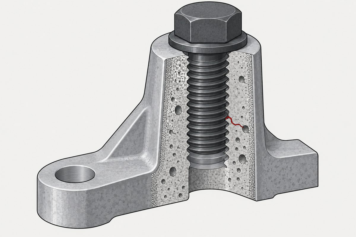
The skin is real, and it is not a constant
Sectioned measurements on high-pressure die cast AlSi10MnMg(Fe) give the fine-grained surface layer as:
| Wall | Skin |
|---|---|
| 2 mm | 30–150 µm |
| 4 mm | 20–90 µm |
| 6 mm | not observed |
| 10 mm | not observed |
And even at 2 mm the skin was found to be locally interrupted, to leave the surface, or to be entirely absent on one side. There is no single typical thickness to quote for HPDC.
The mechanism is straightforward enough. Secondary dendrite arm spacing measured 3.6 µm at the surface against 14.6 µm in the core, which corresponds to cooling rates of roughly 33 °C/s and 0.5 °C/s. The surface froze fast; the core did not.
Porosity does not do what you expect
We were going to write that the skin is dense and the porosity is underneath it, so drilling through the skin exposes the weak part. The measurements do not support that.
| Wall | Core | Skin |
|---|---|---|
| 2.7 mm | 0.18% | 0.42% |
| 3.7 mm | 0.31% | 0.07% |
| 4.7 mm | 0.11% | 0.27% |
| 5.7 mm | 0.14% | 0.16% |
| 6.7 mm | 0.05% | 0.10% |
In four of the five wall thicknesses the skin is more porous than the core, and the same study notes that porosity often peaks at the skin/core interface rather than in either region. A separate study on HPDC AM50 did find gas pores concentrated in the middle third of the wall, with shrinkage porosity more evenly spread — so the distribution depends on the pore mechanism and the process, and neither pattern is a general rule.
For scale: CT resolution in that work was 4 to 9 µm, mean pore diameter 14 to 32 µm, and maximum pore diameter 108 to 247 µm. The largest pores are a meaningful fraction of a small thread.
Hardness does not fall off with depth either
Microhardness mapping across 3 mm sections of two HPDC aluminium alloys gives a U-shaped average depth profile, with about 15 HV between surface and centre on average. Local extremes are much wider: 130 to 150 HV at the surface of one alloy against 50 to 90 HV locally in the core, and as low as 30 to 45 HV at pores.
But a separate AlSi10MnMg(Fe) measurement is more awkward than that: hardness starts near 86 HV at the surface and rises to about 300 µm depth, as the Al–Si eutectic fraction increases, before it starts to decline. So “hard skin, soft core” is not a profile you can assume.
What that means for a thread — carefully
Here is where we have to be honest about what is inference and what is measured.
We could not find any study that resolves thread strength by depth in HPDC, or that compares pull-out for drilled threads at different depths. What we can say is geometric: if the hole is drilled inward from the outside surface, the original skin sits only near the hole mouth, and the cylindrical wall is freshly exposed material. When the engagement length is much greater than tens to hundreds of micrometres, most of the thread is not in the original outer skin.
That is not the same as saying the thread sits in a uniform, weaker core:
- a cast cored hole keeps its own cast skin on the bore, which a drilled hole does not;
- the skin can be interrupted, and the harder region can sit at the skin/core interface;
- porosity is not necessarily highest in the core.
We also could not find a direct comparison of internal threads in HPDC against the same alloy wrought or extruded. The nearest is a bulk tensile comparison — HPDC AZ91 yielding roughly two to three times lower than extruded AZ91 — but no threads were made or tested in it, so it cannot be converted into a thread stripping figure.
What the standards actually give you
-
DIN 7500-2 does address cast skin. Its guidance notes that
hole-making methods that work-harden the wall may need a larger diameter than the
tabulated values, that this may also apply to cast holes — the German text
names Gusshaut explicitly — and that for cast cored holes the screw
geometry, including the forming zone, has to be matched to the cast hole
individually. The values are guidelines from manufacturer and user trials, with
your own testing expected before volume.
The public document is the official introduction; the five-page standard itself is paid, so we are not citing a clause number we cannot verify. - “Two diameters of engagement for aluminium” is not a standard. DIN 7500-2 tabulates hole diameter against material and actual engagement length. ISO 16224:2026 gives calculation methods for bolt fracture, external thread stripping and internal thread stripping. VDI 2230 Blatt 1:2015 clause R10.4.2, equations 205 to 208, computes effective and total engagement from external thread tensile strength, internal thread shear strength, pitch, diameter, tolerance correction and non-load-bearing length. None of them uses a fixed material multiple, and none has an HPDC-specific factor.
- Thread forming into castings has real support. A US Department of Energy programme tested thread-forming fasteners in cast net-shape holes in HPDC A380 aluminium and AZ91D magnesium, driving to screw fracture or internal thread stripping, and concluded the method is technically feasible in production castings. A SAE paper on cast Al 319-T7 found rolled specimens had higher fatigue strength than cut ones, attributed to residual compressive stress — though that was notch and thread-root simulation, not HPDC internal thread pull-out. We found no study comparing form tapping against cutting at the same hole and thread in HPDC aluminium.
A casting also expands about twice as fast as the steel screw in it — temperature moves preload.
So what do you do with the datasheet number
We wanted to end by saying the alloy's tensile strength is of limited help for thread design. That is too strong. The nominal strength is a real input — ISO 16224 and VDI 2230 both use it, or a shear strength derived from it, to calculate stripping.
The accurate version is narrower and still worth the trouble: the nominal tensile strength is necessary but not sufficient. It cannot stand in for the local structure and porosity around your hole, and a die casting has enough variation in both that the calculation is a starting point rather than an answer.
Which is also why DIN 7500-2 says what it says about validating before volume. On a casting, that instruction is not boilerplate.
Where this connects
The forming route and the hole tolerance it needs are in thread-forming screws into metal; the type letter that decides how the thread gets made is in the letters on a tapping screw; when the parent cannot be the nut at all, see when the parent cannot be the nut; and the plastics case, which behaves differently again, is in screws for plastic.
This page covers step 1, the substrate. The whole order is substrate, thread, head, drive, finish, documentation, and why doing it out of order is rework rather than a tweak is in specifying a screw.
Common questions
How thick is the skin on a die casting?
It depends on the wall and it is not always there. Sectioned HPDC AlSi10MnMg(Fe) gave a fine-grained skin of 30 to 150 micrometres on a 2 mm wall and 20 to 90 micrometres on a 4 mm wall, while 6 mm and 10 mm specimens showed no such skin at all. Even at 2 mm the skin was locally interrupted, left the surface, or was entirely absent on one side, so there is no single typical thickness to quote.
Is porosity concentrated in the core of a die casting?
Not reliably. X-ray CT on HPDC AZ91 found the skin more porous than the core in four of five wall thicknesses — 0.42 against 0.18 per cent at 2.7 mm, for instance — and porosity often peaking at the skin to core interface rather than in either region. A separate study on AM50 did find gas pores concentrated in the middle third of the wall with shrinkage porosity more even, so the distribution depends on the pore mechanism and the process.
Does a die casting get softer with depth?
Not monotonically. Microhardness mapping across two HPDC aluminium alloys gives a U-shaped average profile with about 15 HV between surface and centre, and much wider local extremes. But one AlSi10MnMg(Fe) measurement starts near 86 HV at the surface and rises to roughly 300 micrometres depth as the aluminium-silicon eutectic fraction increases, before declining. Hard skin over soft core is not a profile you can assume.
How much thread engagement does a die-cast aluminium boss need?
There is no standard multiple. The two diameters figure is a rule of thumb. DIN 7500-2 tabulates hole diameter against material and actual engagement length; ISO 16224:2026 gives calculation methods for bolt fracture and thread stripping; and VDI 2230 Blatt 1:2015 clause R10.4.2 computes engagement from thread strengths, pitch, diameter, tolerance correction and non-load-bearing length. None uses a fixed material multiple or an HPDC-specific factor.
Can I use the alloy datasheet strength to design the thread?
As an input, yes; as the answer, no. Nominal tensile strength is used by ISO 16224 and VDI 2230, directly or through a derived shear strength, to calculate stripping. But it cannot stand in for the local structure and porosity around your particular hole, and a die casting varies enough in both that the calculation is a starting point. That is also why DIN 7500-2 asks for your own trials before volume production — on a casting that is not boilerplate.
References
- Dalai et al., Metallurgical and Materials Transactions A, DOI 10.1007/s11661-024-07631-1 — skin thickness at 2 mm, SDAS and cooling rate, hardness with depth
- Dalai et al., Materials Characterization 221 (2025) 114775 — skin at 4 mm; absent at 6 mm and 10 mm
- Biswas et al., Metallurgical and Materials Transactions A (2013), DOI 10.1007/s11661-013-1783-y — HPDC AZ91 porosity by CT, skin against core; bulk tensile against extruded
- Chadha et al., Materials Science and Engineering A 427 (2006) 99–111, DOI 10.1016/j.msea.2006.04.082 — AM50 porosity distribution
- Yang et al., “The Skin Effect in High Pressure Die Casting Al Alloys”, ICAA12 (2010) — U-shaped hardness profile
- DIN 7500-2:2016-04 — hole diameter guidance; work-hardened and cast holes, Gusshaut; individual matching for cast cored holes
- ISO 16224:2026; VDI 2230 Blatt 1:2015 clause R10.4.2, equations 205–208 — engagement by calculation, not a fixed multiple
- Paxton et al., PNNL/DOE, “Die-Cast Net-Shaped Hole Process Development for Application of Thread-Forming Fasteners”, FY2006 Automotive Lightweighting Materials Progress Report
- Blaha et al., SAE 2006-01-0780, DOI 10.4271/2006-01-0780 — rolled against cut, cast Al 319-T7
Acceptance for any particular joint is governed by your drawing and your own testing.
Enquiries
If the part is a casting, tell us whether the hole is cast or drilled and roughly how thick the wall is there. Those two change the answer more than the alloy name does.
Request a quotation
Tell us the part and the quantity. We will come back on feasibility, lead time and price.
Or email us directly sales@tigerfasteners.com