 TIGERFASTENERS
Most Reasons for Studs Are Reasons for Tapped Holes
Someone in the fuels industry asked why their site specifies studs on pipeline flanges and was told it was industry standard, with no reason attached. The best-voted answer listed four advantages, then edited itself to say those four did not apply. Two more engineers made the identical mistake in the same thread. All three had read one word as a different joint.
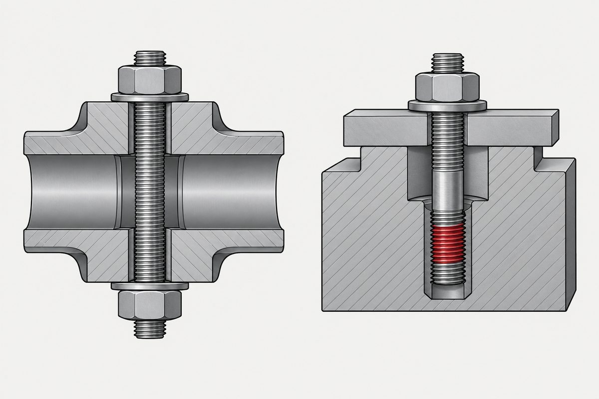
One word, two questions
ASME PCC-1, the assembly guideline the pipeline world actually works to, does not sort bolting into studs and bolts at all. Appendix N defines a bolt with integral head as a fastener with a fixed head on one end and either a nut or a drilled and tapped hole on the other, and a bolt without integral head as a fully threaded fastener using either two nuts or one nut and a drilled and tapped hole.
Read that twice and the shape appears. There are two independent questions. Is there an integral head? And is the far side a nut or a tapped hole? Two questions give four joints, and the word “stud” covers two of them: the fully threaded rod with a nut on each end, and the fastener whose metal end lives permanently in a tapped hole. Those two behave differently, and almost every advantage anyone recites belongs to the second one.
PCC-1 goes further than declining to distinguish them. A footnote on its first working page states that throughout the document “bolt” is an all-inclusive term covering a bolt, stud, stud bolt or cap screw. The industry whose practice is quoted as studs are preferred wrote a guideline that refuses to let the noun carry any load at all. That is the reason nobody at the site could give a reason.
The other axis, the one about whether the female thread is a purchased nut or a hole in your own part, is set out in machine screw or bolt. This page is about the head.
What the tapped hole changes, with a number
PCC-1 has a troubleshooting appendix for joints that leak repeatedly, and it names the single-flange joint directly. A joint made of one flange with bolts threaded into tapped holes is inherently less flexible and generally more troublesome, because the effective stretching length of the bolts is shorter. It is less tolerant of gasket thickness loss and of differential thermal expansion. The appendix then quantifies it: such a joint suffers roughly twice the bolt load loss for every 0.02 mm (0.001 in.) of gasket thickness lost after assembly.
That is a real engineering difference, it is written down, and it has nothing to do with whether the fastener has a head. It follows from there being one flange instead of two. Why a short bolt is a worse spring than a long one is the bolt is a spring.
The bookkeeping is worth seeing, because it settles a related myth. PCC-1 takes the effective stretching length of a through-bolted joint as the distance between the mid-thickness of the two nuts, a heavy hex nut being one nominal diameter thick. For the portion of a fastener studded into a tapped hole it takes half a nominal diameter. Half a diameter each way. By this model the tapped hole and the nut contribute the same length, so the tapped hole is not penalised for being a tapped hole. The joint is shorter because there is one flange in it.
What the tapped hole genuinely costs you is what happens when its thread is damaged. PCC-1 asks you to check tapped-hole threads for free running by hand exactly as you check nut threads, and points at ASME PCC-2 Article 303 when they are damaged. That is a repair procedure rather than a parts swap, which is the accurate version of the common shop claim that a galled tapped hole means scrapping the vessel. There is a documented way back. It is a bad day, not a write-off. What can and cannot be put back into a damaged female thread is nothing fills a stripped thread.
What removing the head actually changes
The honest list is shorter than the folklore, and every item on it is about assembly and disassembly rather than about strength.
- It does not save you a wrench. PCC-1 defines a backup wrench as the tool used to secure the nut or bolt head opposite the one being turned. Two nuts on a threaded rod need one just as a headed bolt does. The configuration that removes the backup wrench is the tapped hole, which is a different question.
- You choose which end carries the spare thread. PCC-1 recommends fully engaging the nut on one end so that no thread projects there, putting all the excess on the opposite end, because excess protrusion collects corrosion and paint and makes the joint hard to open. With two threaded ends you can put the spare where you want it.
- Tensioning needs thread to grip. A hydraulic tensioner requires the thread to extend at least one bolt diameter beyond the outer nut face on the tensioner side. A headless fastener offers that on either side.
- The washer was designed for the nut end. The through-hardened washer specification in PCC-1 says its bore was chosen so it can be used under the nut, and that using it under a bolt head may interfere with the shank or the underhead fillet. Why that fillet is not a detail is the fillet under the head.
- Two nuts give two attempts. This one is field practice rather than a clause, and worth stating as such: if one nut seizes you still have an unspoiled thread and an intact nut at the other end. PCC-1 supports the underlying worry with a specific remedy, noting that galling incidents with SA-193 Gr B7 bolting are avoided by using the higher strength SA-194 Gr 4 nut rather than Gr 2 or 2H. See also why stainless galls.
The claim that studs twist less
This one circulates widely and deserves a careful answer, because a version of it is true and the usual version is not.
PCC-1 does say that a fastener tightened by hydraulic tensioning lives longer, with less risk on reuse, and it gives the reason: no torsion and no thread galling, because the nut is wound down while the fastener is unloaded. That is an argument for the method. We read the document looking for any clause crediting a headless fastener with lower torsion under a torque wrench and did not find one. When you turn a nut against thread friction, the fastener carries that thread torque whether or not the other end has a forged head on it.
The practical reading is that if torsion is your problem, the fix on offer in the guideline is tensioning rather than a change of part. Where the torque you apply actually goes is torque and clamp force, and what the number silently assumes about friction is a torque spec assumes a friction condition.
The other stud: its two ends are not the same thread
The joint most people picture when they hear the word is the one with a metal end living permanently in a tapped hole, cylinder head studs being the everyday example. For that part the two ends differ in more than length, and the difference is specified.
The Indian standard for studs, IS 1862, splits them into three types by the length of the metal end: Type A at about one diameter for use in steel, Type B at about 1.5 diameters for cast iron, Type C at about two diameters for aluminium alloys. The same standard sends the metal end thread to a separate document, IS 2186, for external interference fit threads. The end that goes into the parent is not simply longer. It is a different fit, which is what keeps the stud in place when the nut comes off.
Three national standards have written that table down and no two of them agree.
| Standard | Metal end lengths | Parent material named? |
|---|---|---|
| IS 1862 | 1 d, 1.5 d, 2 d | Yes, one to one: steel, cast iron, aluminium alloys |
| JIS B 1173 | about 1.25 d, 1.5 d, 2 d | Yes, but not one to one |
| DIN 938 / 939 / 835 / 940 | about 1 d, 1.25 d, 2 d, 2.5 d | No. The titles carry the length and stop |
The Japanese entry is the one worth reading twice. JIS B 1173 offers three metal-end lengths and then says in a note to its dimension table that types 1 and 2 are both for studding into steel, cast steel and forged steel included, or cast iron, and that type 3 is for light alloys. The standard with the material column declines to tell you whether steel takes 1.25 d or 1.5 d. That is not an omission. Length of engagement follows from the strength of the two threads rather than from the name of the parent, which is thread engagement, and why the published rules for it disagree is the engagement rules disagree.
Read across the table and the cast-iron row moves from 1.25 d to 1.5 d depending on whose catalogue is open. A drawing that says only “stud, M12” has not told the supplier which of these parts to make.
How to ask the question so it has an answer
The thread on r/AskEngineers ran to 125 comments and never resolved, because “studs or bolts” is two questions wearing one name. Split them and both have answers.
- Is the far side a nut or a tapped hole? This decides joint stiffness, how the joint tolerates gasket relaxation, and what happens when a thread is damaged. It is where the engineering lives.
- Is there an integral head? This decides how the joint is assembled and taken apart, which end carries spare thread, whether a tensioner fits, and which washer is legitimate.
If the answer that comes back is still industry standard, the question to ask next is which of the two it refers to. In the guideline that the phrase points at, the noun means all four.
The same choice appears at rack scale, where a standard declines to make it: EIA-310-D allows the rail holes to be round, square or tapped, so the thread can live in the rail, in a cage nut, or on the far side.
This is not one of the six steps. It shows up across them, or after assembly. Where the decisions that lead here were made is in specifying a screw, which sets out the order and why doing it out of order is rework.
Common questions
Is a stud stronger than a bolt of the same grade and diameter?
Nothing in ASME PCC-1 says so, and its bolt load and stretch calculations do not distinguish the two. The effective stretching length model treats a nut and a tapped hole as contributing the same half diameter each, and the material grade is set by the material specification rather than by whether a head was forged on. The claim that upset heading disturbs the grain flow and leaves a crack starter is repeated in workshops, but we found no clause or published test supporting it as a general ranking, so it is not a basis for substitution.
Our fitters only put the torque wrench on one nut. Is that wrong?
No. One nut is turned and the other is held, which is what PCC-1 means by a backup wrench: the tool used to secure the nut or bolt head opposite the one being turned. The same applies to a headed bolt, where the head is the thing being held. What matters is that the far side does not rotate, not which side the torque wrench sits on.
Why are single-flange joints more likely to leak?
PCC-1 attributes it to the shorter effective stretching length. A joint made of one flange with bolts into tapped holes is stiffer, so the same small loss of gasket thickness releases more bolt load. The appendix puts it at roughly twice the load loss for each 0.02 mm of thickness lost after assembly, and suggests increasing bolt flexibility with extension collars and longer bolts where that is a problem.
Does a stud avoid twisting the fastener during tightening?
Not by itself. PCC-1 credits the absence of torsion to hydraulic tensioning, where the nut is wound down while the fastener is unloaded, rather than to the fastener having no head. Under a torque wrench the thread friction torque is carried by the fastener either way.
A drawing says stud M12x60 and nothing else. Is that enough to order?
Not if the metal end goes into a tapped hole. The length of the metal end is a separate decision: IS 1862 gives about 1 d for steel, 1.5 d for cast iron and 2 d for aluminium alloys, while the DIN series offers 1 d, 1.25 d, 2 d and 2.5 d as four separate standards without naming a material. IS 1862 also sends the metal end thread to an interference fit specification. Name the standard and the parent material, or say which end goes where.
References
- ASME PCC-1 — Guidelines for Pressure Boundary Bolted Flange Joint Assembly (2019 edition read: Appendix N-1 definitions, para. 8.2 and 8.2.1, para. 10.2, Appendix A-1.2, Appendix M-1.2, Appendix P-4.2.1, Appendix Q-4.2)
- ASME PCC-2, Article 303 — repair of damaged tapped hole threads
- IS 1862:1975 — Specification for Studs (Second Revision); Amendment No. 1, March 1981, Types A, B and C
- DIN 938 — Studs, metal end approximately 1 d (sister standards DIN 939, DIN 835, DIN 940)
- JIS B 1173 — Studs; Table 1 note 3 gives the type 1, 2 and 3 metal end lengths and the parent materials they are intended for
The PCC-1 text read for this page was the 2019 edition; the current purchasing edition is later and clause numbers should be checked against it before being quoted in a procedure. The PCC-1 footnote pointing to complete thread engagement cites ASME BPVC Section VIII Division 1 UG-13 and ASME B31.3 para. 335.2.3, which were not read directly here. The DIN metal-end lengths come from the standard titles themselves; the mapping from metal-end length to parent material appears in IS 1862 and is not stated in the DIN titles, so the two should not be merged. JIS B 1173 was read on a public mirror of the standard text rather than on a copy purchased from the Japanese Standards Association; the note quoted is note 3 to the dimension table, and its wording is that the lengths are equal or close to 1.25 d, 1.5 d and 2 d rather than exactly those values. The two-nuts-two-attempts point is field practice and is not a clause in any document read for this page.
Enquiries
If the enquiry says “stud”, tell us which end goes where. A fully threaded rod with a nut at each end and a stud whose metal end lives in a tapped hole are different parts with different thread specifications, and the second one needs the parent material named before the metal end length can be chosen.
Request a quotation
Tell us the part and the quantity. We will come back on feasibility, lead time and price.
Or email us directly sales@tigerfasteners.com