 TIGERFASTENERS
A compliant rack can have three different holes, so compliant is not the same as it fits
Read about six minutes. A 19-inch rack looks like the most standardised object in a data centre, and in the dimension that matters most it is: the hole pattern has not moved in decades. What the standard does not do is pick one kind of hole. Round, square and tapped are all allowed, and a vendor guide from Intel says plainly that its rail kits do not work with one of the three.
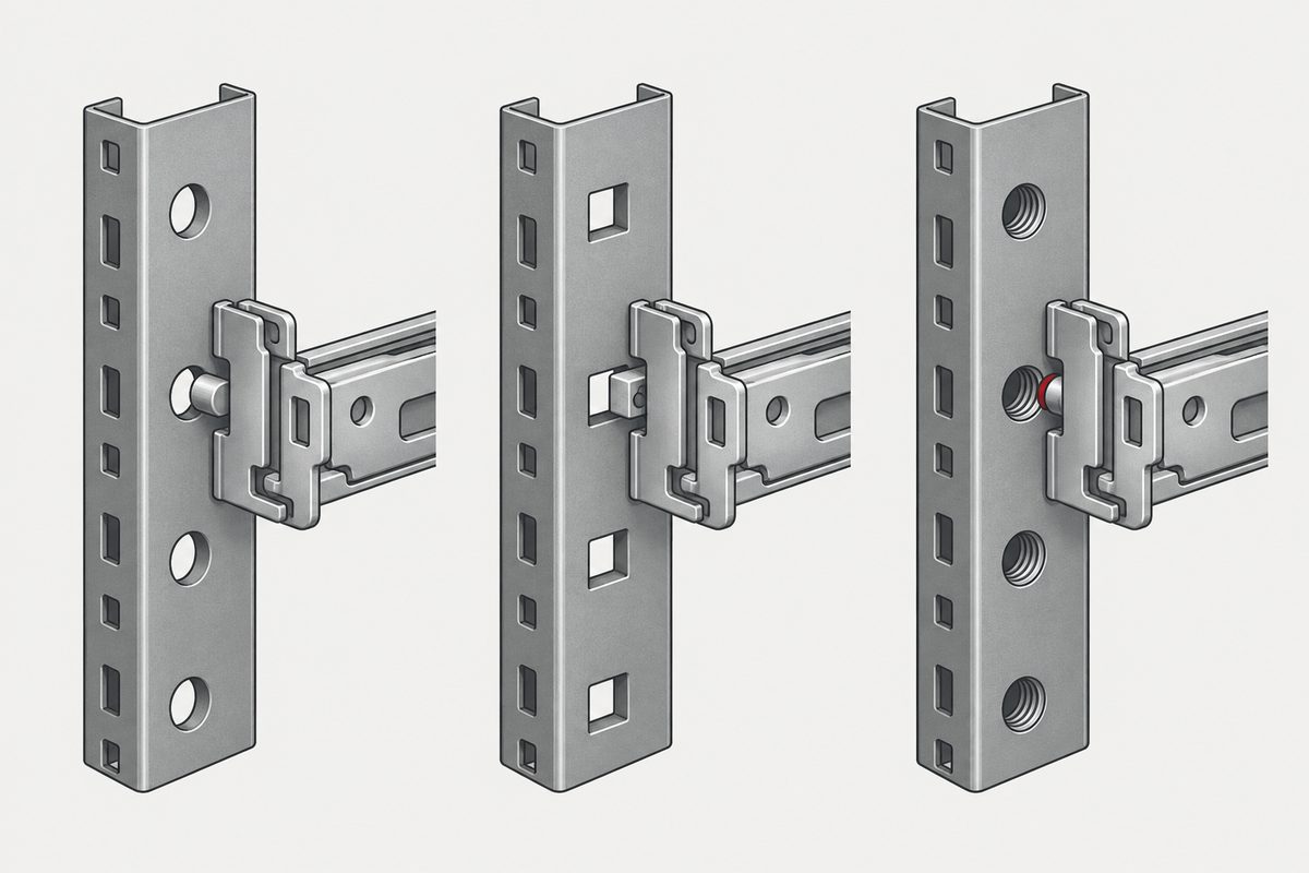
Three hole forms, all of them compliant
Intel published a compatibility guide for server rack cabinets, and its note on mounting flange holes is the shortest way into this:
While EIA-310-D allows the mounting flange holes to be round, square, or tapped (threaded), Intel railkit hardware is only designed to work with round or square holes, but not tapped holes. Intel mounting brackets work best with square holes.
Two facts sit in that sentence. The standard permits three forms of hole, and a major server vendor’s mounting hardware does not work with one of them. Neither party is in breach. A rack with tapped holes is compliant, the rail kit is designed to the same standard, and they do not go together.
One caveat belongs here rather than at the end. The edition Intel names is EIA-310-D, published in 1992, and Intel’s guide is dated September 2005. A later edition, EIA/ECA-310-E, came out in December 2005 and is the current one. Everything quoted on this page therefore describes the -D era, and what the current edition says about hole forms or threads we do not know, because we have not read it.
That is a different failure from a missing specification. Nothing was left out by accident. The standard was written to accommodate racks that already existed, and the cost of accommodating them lands on whoever is holding a server at chest height in front of the wrong rack.
What the square hole is actually for
A square hole holds no thread. That is not a limitation being worked around; it is the point. The thread arrives separately, in a cage nut pushed into the square hole from behind, and it leaves the same way. A stripped thread costs one cage nut rather than a rail, and the same rack takes a different thread next time by taking a different nut.
A tapped rail makes the opposite trade. The thread is there, in the correct place, with nothing to fit or drop; and it is permanent, single-valued and destructible. Strip it and the repair is at the rail.
So the three hole forms are not three qualities of the same thing. They are three positions on where the thread lives: in the rail, in a consumable, or nowhere at all — because a round hole takes a bolt through to a nut on the far side. Neither trade is one-way: a stripped tapped rail can often be re-tapped or fitted with a thread insert, so the difference is where the repair happens and how routine it is, not whether repair is possible. Our page on what a tapped hole changes works through the same choice at the scale of a single joint.
The pattern is imperial, whatever units it is printed in
IBM publishes the geometry as an installation requirement for racks it did not supply, citing the same standard: the rack must meet EIA-310-D, the rail-mounting holes must be 465 mm ± 1.6 mm apart on centre, and the holes come in sets of three spaced 15.9, 15.9 and 12.7 mm on centre. Written in inches those three are 0.625, 0.625 and 0.5, and they convert exactly:
| Gap | Inches | Millimetres |
|---|---|---|
| First | 0.5 | 12.7 |
| Second | 0.625 | 15.875 |
| Third | 0.625 | 15.875 |
| One rack unit | 1.75 | 44.45 |
The three gaps sum to 1.75 inches exactly, which is the rack unit Intel’s guide defines as 1.75 inches or 44.45 millimetres. Every millimetre figure in that table is an exact conversion of the inch above it: 0.625 × 25.4 = 15.875, and 1.75 × 25.4 = 44.45. The 19 inches in the name is 482.6 mm on the nose.
None of those metric numbers is a round number, because none of them was chosen in metric. A rack unit is not 44 or 45 millimetres, and it never will be. Published tables often round 15.875 to 15.9, as IBM’s does, which is a printing decision rather than a dimensional one.
The square hole itself is the exception, and it is worth noticing because it marks the boundary of the argument. IBM gives it as 9.5 mm (0.37 in.) ± 0.1 mm. Three eighths of an inch is 9.525 mm, so 9.5 is not that number rounded — it is a metric dimension with an approximate inch conversion beside it, which is the opposite of every figure in the table above. One rail carries dimensions from both systems, and which one is native tells you which came first.
The second way a compliant rack refuses a compliant server
The same Intel guide names something the standard does not cover at all:
The EIA-310-D standard does not address the issue of “rack angle clearance”.
It goes on to give a figure of its own: a minimum of 16.77 mm of clearance between the two edges of the mounting flange, which it calls absolutely critical for the proper mounting of its slide rails, and it notes that many rack vendors ship a U-shaped flange instead of the L-shaped one that leaves that room.
So there are two distinct mechanisms in one document. One is the standard permitting three options, and the other is the standard being silent on a dimension that decides whether the hardware fits. The guide’s own advice about buying reads accordingly: not all rack cabinets are built to EIA-310-D specifications, so be sure and ask.
What this page did not establish
- No standard was read. EIA-310-D, IEC 60297 and DIN 41494 are all paid documents. That EIA-310-D permits round, square or tapped holes is what Intel’s guide reports about it, not something we read in the standard. Copies of EIA-310-D circulate on file-sharing sites; we did not download or cite one.
- The geometry is a vendor requirement, not the standard. The spacing, the square hole size and the rail-to-rail figure are quoted from IBM’s installation specification for racks it did not supply, which cites EIA-310-D rather than reproducing it. The thread sizes come from a general reference work, which is weaker again and is named as such below. The arithmetic on all of it is ours and can be checked with a calculator.
- We found no general standard for the cage nut itself. A cross-check looked for one covering the body, the spring cage, panel thickness range and load, and did not find it; the internal thread is governed by ordinary thread standards and the rest appears to sit in manufacturers’ catalogues. That is a search that came up empty, not a proof that nothing exists.
- The Intel guide is from 2005, and so is the edition question. Revision 2.4 is dated September 2005 and cites EIA-310-D of 1992. EIA/ECA-310-E followed in December 2005 and is the current edition, maintained by ECIA. A cross-check also found a claim that later editions list permitted threads for tapped holes, with preferred options. If that is right, a page arguing that the standard declines to pick a thread would be wrong about the current edition. This page does not make that argument — it reports what one vendor said about hole forms under -D — but the distinction is the reason the argument is kept that narrow.
- No cage nut dimensions or loads appear here. We have no document to cite for them, so this page describes what a cage nut is for and gives no numbers.
- IEC 60297 and DIN 41494 are named only. Whether they permit the same three hole forms, or fewer, we do not know.
This is not one of the six steps. It shows up across them, or after assembly. Where the decisions that lead here were made is in specifying a screw, which sets out the order and why doing it out of order is rework.
Common questions
Does EIA-310-D specify a thread for rack mounting holes?
According to Intel’s server rack cabinet compatibility guide, the standard allows the mounting flange holes to be round, square, or tapped. That means a threaded hole is one permitted option rather than the specification. We have not read the standard itself, which is a paid document, so this is what a vendor guide reports about it.
Why do 10-32, 12-24 and M6 all turn up in racks?
Because on a square-hole rack the thread is not in the rack at all. It arrives in the cage nut you push into the square hole, so the same rail accepts whichever thread the nut carries. On a tapped rail the thread is fixed, and general references describe those as usually 10-32 UNF and less often 6 mm metric. Those three are the common ones rather than a closed list — M5 cage nuts are also sold — which is what you would expect when the thread is a property of the nut instead of the rack.
What is a rack unit in millimetres?
One U is 1.75 inches, which Intel’s guide gives as 44.45 mm. It is not a round metric number because it was not chosen in metric: 1.75 × 25.4 = 44.45 exactly. The three vertical gaps that make up a rack unit are 0.5, 0.625 and 0.625 inches, and those sum to 1.75 exactly.
Can a rack be compliant and still not take my server?
Yes, in at least two ways that one vendor guide documents. Intel states its rail kits work with round or square holes but not tapped ones, all three of which the standard allows. And it states that the standard does not address rack angle clearance, while giving a minimum of 16.77 mm between the mounting flange edges as critical for its slide rails.
Why use square holes rather than tapped ones?
Because the thread becomes a consumable. A square hole holds no thread; the thread arrives in a cage nut and leaves the same way. Stripping one costs a nut rather than a rail, and changing thread type is a matter of changing nuts. A tapped rail trades that away for a thread that is already in place and cannot be dropped during installation.
References
- Intel, Server Rack Cabinet Compatibility Guide, Revision 2.4, September 2005 — the note that EIA-310-D allows round, square or tapped mounting flange holes while Intel rail kits do not work with tapped ones; the rack unit definition; and the statement that the standard does not address rack angle clearance (free PDF)
- IBM, rack installation specifications for racks not purchased from IBM — the requirement to meet EIA-310-D, the 465 ± 1.6 mm rail spacing, the 15.9 / 15.9 / 12.7 mm hole sets and the 9.5 ± 0.1 mm square hole
- 19-inch rack — general reference used here only for the usual tapped thread sizes; a secondary source, flagged as such
The Intel guide was downloaded, converted with pdftotext and read directly; all three quotations attributed to it are verbatim. It is a named vendor’s technical guide rather than a standard, and it is dated September 2005. No standard was read for this page: EIA-310-D, IEC 60297 and DIN 41494 are paid documents, and although copies of EIA-310-D circulate on file-sharing sites we did not download, read or cite one — the statement that the standard permits three hole forms is Intel reporting on it. The hole spacing pattern and rail-to-rail figures come from a general reference work rather than a standard or a manufacturer drawing, which is a weaker source than this site normally relies on; it is named in the references above rather than blended in. The arithmetic is ours and can be repeated with a calculator: 0.5 + 0.625 + 0.625 = 1.75 inches, 0.625 × 25.4 = 15.875 mm, 1.75 × 25.4 = 44.45 mm, 19 × 25.4 = 482.6 mm. Where published tables show 15.88 rather than 15.875, that is rounding in the printing, not a different dimension.
Enquiries
If you are fastening into rack hardware and the thread has to be decided rather than inherited, tell us which hole form the rail has. That decides whether the thread is in the rail, in a nut you supply, or on the far side of the panel.
Request a quotation
Tell us the part and the quantity. We will come back on feasibility, lead time and price.
Or email us directly sales@tigerfasteners.com