 TIGERFASTENERS
Why every source gives a different minimum thread engagement
Someone on an engineering forum tried to calculate minimum thread engagement properly and got stuck on something odd: the standard internal-thread shear area formula wants engagement length as an input, and engagement length is what they were solving for. Thirty-three replies arrived. Not one of them addressed that. They gave eight different multipliers instead — and two of those replies were right in a way the other six were not.
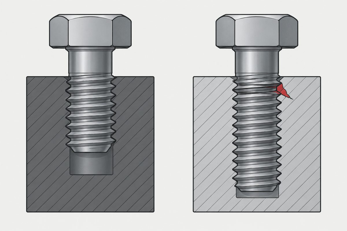
The formula looks circular, and the observation is correct
To check whether the female thread will strip before the screw breaks, you compare two things: the shear area of the internal thread and the tensile stress area of the screw. The shear area expression contains Le, the length of engagement.
So if you are trying to find the engagement length, the formula appears to require the answer before it will produce it. That is a fair reading and it is why the question gets asked. The way out is not complicated, but nobody mentions it, because everyone answers a different question — the one they already have a number for.
Eight rules, one discussion, all of them confident
Counted from a single thread, the answers offered were: one and a half times the nominal diameter; one and a quarter times; a minimum of six threads; six to eight threads; one times the major diameter when the materials match; one and a half to two in steel, after which "you don't gain any strength"; one diameter rising to two in annealed steel; and one reply pointing out that the nut supplied with the bolt already settles it.
None of those is stupid, and several are useful. They are also not compatible, and the person asking has no way to tell which assumptions each one carries. That is the actual problem — not that the rules are wrong, but that a rule stated as a bare multiple has thrown away the information you would need to check whether it applies to you.
So pick the most conservative one — except two of them are a different kind of answer
Two replies in that thread said something structurally different from the other six. One: if the materials differ, scale the engagement by the ratio of their strengths — if the parent is half the yield strength of the bolt, use two diameters. The other: one and a quarter diameters for matching materials, multiplied by the ratio of shear strengths when they do not match.
Those are not multipliers. They are the multiplier's source. Several of the other six are that same calculation, already run for one assumed material pair and then stated without the assumption. Not all of them — a fixed thread count carries a pitch assumption instead, and the standard nut answer rests on proof load and thread form rather than on a material ratio. Which is why eight of them can coexist: each is correct for the pairing its author had in mind, and none of them says what that was.
What the ratio does to a bad idea, in one line
The person asking had a real job: hold roughly 7,400 lb of lead ballast onto a boat with lag screws, as a temporary measure. Someone ran the ratio. Lead's yield strength is on the order of a twenty-fifth of the bronze screw's, so the engagement needs to be about twenty-five times what it would be into a matching material. Against a one-diameter baseline that is about 19 inches of thread on a three-quarter-inch screw — and the reply that worked it through put it nearer two and a half feet, which depends on the baseline you start from. Either figure settles the question.
The absurd answer is the useful one. No multiple-of-diameter rule would have produced it, because no such rule contains lead. The ratio method produces a number you can immediately see is impossible, which is the fastest way to learn that the joint has to be designed differently — in that case by clamping the ballast rather than threading into it.
Why the same rule keeps producing different numbers
"Aluminium" is not one material. Working the ratio for an M8 8.8 screw and asking how much engagement stops the female thread failing first:
| Parent material | Approx. shear strength | Multiple |
|---|---|---|
| Steel S235 (0.6 × Rm,min) | ~216 MPa | 0.77 |
| Aluminium 6061-T6 | ~207 MPa | 0.80 |
| Grey cast iron EN-GJL-150 | ~170 MPa | 0.98 |
| Aluminium 6063-T5 | ~117 MPa | 1.42 |
| Aluminium 5052-H32 | ~138 MPa | 1.21 |
| Zamak 3 die casting | ~214 MPa | 0.78 |
The steel row is 0.77, and everyone says one diameter. That gap is the point of the whole table. 0.77 is the bare geometric figure: basic-profile areas, nominal strengths, nothing else. One diameter is that number after nut dilation, the first engaged thread taking a disproportionate share of the load, tolerance limits and real material sitting under nominal have each been allowed for. The gap is about 30%, and how it divides between those effects is not something this article measures.
So every rule in that thread is a geometric number plus somebody's margin, and neither half is stated. Two rules can differ because the materials differ, or because one author was more cautious, and from the multiple alone you cannot tell which.
Shear strengths above are published typical values for the named alloy and temper — aluminium figures from alloy datasheets, Zamak from the zinc association's property tables, grey iron from EN-GJL grade data. The steel row is not a published shear strength: it is 0.6 × minimum tensile, which is a conversion, not a measurement. Every one of these moves with temper and casting practice, so treat them as the shape of the answer rather than as your material.
6061-T6 and 5052-H32 are 50% apart, and a catalogue calls both of them aluminium. One of them lands near a steel screw's requirement and the other well past it. So a rule that says "aluminium needs 2D" is not being careless — it is being safe across a range it does not name.
The size effect people expect is much smaller. Running the same comparison from M2 to M12 changes the strength ratio by about 13%, so "bigger screws need proportionally more" contributes far less than the material does. It is the wrong thing to worry about first.
So the circularity, and how to get out of it
It is not circular. The shear area is linear in Le, so the equation rearranges and gives you the answer in one step:
Le = As · σscrew ÷ (0.875 · π · d · τparent)
For M8 class 8.8 into S235: 36.6 mm² × 800 MPa, divided by 0.875 × π × 8 × 216 — 6.2 mm, or 0.77 diameters. No iteration, no guessing.
The reason nobody in that thread said so is that nobody was answering the question asked. The asker had spotted something real and the answer is simply that the appearance of circularity is an artefact of how the formula is usually written — as a capacity check with Le as an input, rather than solved for the quantity you want.
The two numbers you need are the parent's shear strength and the screw's class. Once those are on the page, the multiple falls out on its own — and you will know which of those eight rules you have just reproduced. See how long the engagement should be for the design targets, and what the property class numbers mean for the screw half of the ratio.
What this does not cover
- The shear strengths above are typical published values, not measured ones. Real supply varies with temper, and aluminium tempers vary a lot more than the grade name suggests.
- The model is basic-profile geometry. It ignores nut dilation, the uneven load sharing that puts most of the force on the first engaged thread, and tolerance limits, all of which reduce real capacity below the geometric figure.
- It says nothing about fatigue, and nothing about how the joint is loaded. For anything carrying life-safety loads, this is the wrong depth of analysis — VDI 2230 is the document that goes properly.
And if you went looking for an ISO standard to settle it, there is a table of engagement lengths, but it exists to choose a tolerance grade rather than a strength. Its normal band happens to run from half a diameter to one and a half, which is where the most quoted multiple comes from.
This page covers step 2, the thread. The whole order is substrate, thread, head, drive, finish, documentation, and why doing it out of order is rework rather than a tweak is in specifying a screw.
Common questions
Why does the thread engagement formula ask for the answer as an input?
Because it computes a capacity from a length, not a length from a capacity. You assume an engagement, work out what the internal thread and the screw can each carry, compare them, and adjust. Two or three passes converge, and each pass shows you the margin rather than just a number.
Which rule of thumb should I use?
They are all the ratio calculation already run for an assumed material pair, so the honest answer is to run it for yours. If you need one number, one diameter for steel into steel is the underlying case and everything else scales up from there by the ratio of the parent shear strength to the screw tensile strength.
Is 2D right for aluminium?
It is safe across a range rather than correct for a grade. For an M8 class 8.8 screw, 6061-T6 works out around 0.80 diameters and 5052-H32 around 1.21, so a single rule covering both has to sit above the worse case with margin. If you know the alloy and temper you can do better than the rule.
Do bigger screws need proportionally more engagement?
Barely. Running the same comparison from M2 to M12 changes the ratio by about 13%, which is small next to the 50% between two aluminium grades. Material first, size second.
What if the parent is much softer, like lead or a plastic?
The ratio still works and it will tell you the joint is wrong. A bronze screw into lead needs roughly twenty-five times the matched-material engagement, which is about two and a half feet on a three-quarter-inch screw. That is the calculation telling you to clamp the part rather than thread into it.
Enquiries
Not sure how much engagement a soft parent actually needs? Send the parent material and temper, the screw size and the class. We will run the ratio and tell you the engagement — and if the answer is that the joint needs an insert or a through-bolt instead, we will say that.
Request a quotation
Tell us the part and the quantity. We will come back on feasibility, lead time and price.
Or email us directly sales@tigerfasteners.com