 TIGERFASTENERS
Where a tapping screw's torque spec comes from
The short version. You have a screw going into sheet metal or a moulded part, and you want to know what to set the driver to. This is where that number comes from.
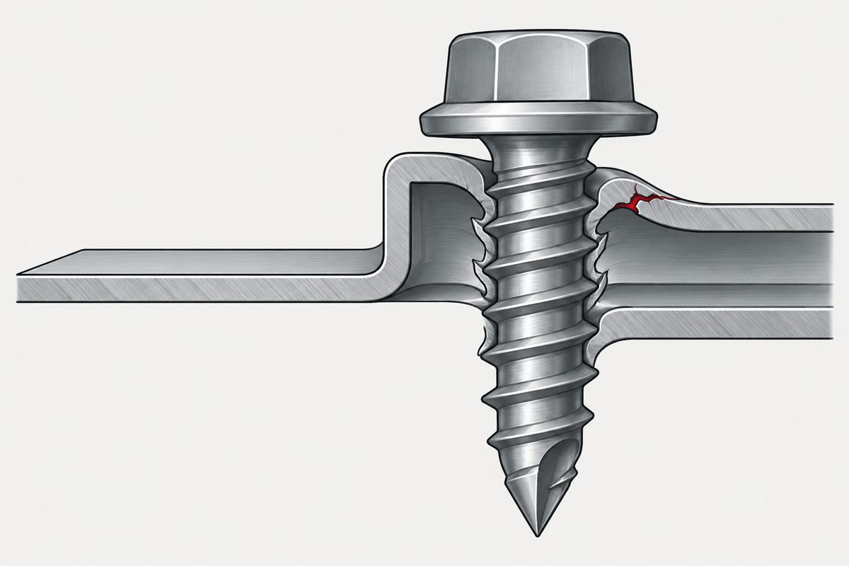
A bolt and nut is “decide how tight, then work out the torque”. A tapping screw is not set that way. ISO 2702 says plainly that these screws are not designed to be tightened to a target force. So the torque is not calculated — it is found by seeing where the joint breaks and staying safely under it.
But that sentence covers less ground than “no nut”, so do not stretch it. It is about screws that cut their own thread in sheet. A screw going into a hole that already has a thread, or into a metal insert, is still the “decide how tight” case.
It is a completely reasonable thing to ask
Machine screws into tapped holes have torque tables. Everyone uses them, they are printed in handbooks, and a line worker can set a driver from one. So asking for the same table for tapping screws is asking for consistency, not for a favour.
The answer that comes back is a range, or a procedure, or a recommendation to test. That sounds like nobody has bothered to work it out.
So what torque do we use — and why nobody will tell you
Ask how torque specs get set and you get a good answer, and everyone gives the same one: first decide how hard the joint needs to be squeezed together — engineers call that preload, and in plain terms it is the force the screw uses to press the two parts against each other — then use T = K · D · F to work backwards to the torque that gets you there.
That answer is correct. It is also entirely about a bolt with a nut on the other end.
Ask the follow-up — what about when there is no nut? — and the thread usually goes quiet.
Part of the reason is that “no nut” is not one case. It is two.
- Into a hole that already has a thread, or into a metal insert — the thread is already there. This is still the “decide how tight” case, and the bolted method largely applies.
- The screw cuts its own thread in sheet (a tapping screw) — a different animal, and the one this page is about.
In small-fastener work — sheet metal and moulded parts especially — the second is the normal case.
What the standard actually says, and how far it reaches
ISO 2702:2022 covers heat-treated steel tapping screws, sizes ST2,2 to ST9,5, and the same paragraph says what they are for: cutting their own thread in sheet metal. Within that scope it says:
Tapping screws are not intended to be pretensioned by design, even though they can experience varying degrees of low-level tensile stress after installation.
In plain terms: this kind of screw was never designed to be tightened to a force. The whole point of T = K · D · F is to work out the torque that reaches a target tightness. If tightness is not what this joint is designed around, that equation is not the tool for the job here. The numbers that govern have to be measured on your own parts.
That sentence is easy to stretch too far, so be careful. It is only about tapping screws cutting their own thread in sheet. It is not a rule that clamp load stops mattering whenever there is no nut. The counterexamples are concrete:
- Screws into tapped holes or metal inserts are designed around clamp load.
- Some screw systems made specifically for plastics are too — suppliers even provide clamp-load calculation against VDI 2230.
- Published work on thread-forming screws separates the cutting stage from the tightening stage, and builds a torque-to-clamp-load relationship for the second one.
So the real dividing line is whether the joint sets out to control clamp load — not whether a nut is present.
One more place this gets misread. The standard does not say there is no force in the joint. It says the screw is not designed to be tightened to a force, while accepting that some tension exists once it is in. There is force. What there is not is a target number you are aiming a torque wrench at.
So how is the torque set? Look at the gap between two numbers
Two torques frame the problem, and neither of them is clamp load:
| Torque | What it is | What moves it |
|---|---|---|
| Driving torque (how hard it is to drive in) |
What it takes to cut the thread and run the screw all the way down | Hole size, material, thread form, coating, lubrication |
| Governing failure torque (where it breaks) |
Whichever of two failures comes first: the thread in the part tears out, or the screw twists off | Engagement length, substrate strength, and the screw's own torsional strength |
What you want is those two numbers far apart. The lower the torque needed to drive it in, and the higher the torque where it breaks, the wider the band in the middle — and the easier it is for a production driver to land inside it.
So for this kind of joint, a good screw is not the strongest one. It is the one that goes in easily and is hard to break. Simply making the screw stronger does not automatically widen the band, because a stronger screw can also be harder to drive.
Do not treat that band as the whole of assembly safety either. Driver accuracy, when it shuts off, friction under the head, and the spread of hole size and material thickness across production all eat into it. And it has to be measured on real parts, not calculated from catalogue figures.
Manufacturer engineering guidance, referencing ISO 2702, puts approximate numbers on it — these are guide values from a supplier handbook, not requirements from the standard:
- Sheet-metal tapping screws: tightening torque at roughly 80% of the governing lower failure torque — the screw's minimum torsional strength or failure of the component thread.
- Sheet-metal tapping screws: maximum thread-forming torque below 50% of the screw's minimum torsional strength.
- Direct fastening into thermoplastics (a different section of the same handbook): make the measured gap between driving torque and stripping torque as large as possible.
These three come from different situations. They are not one rule, and they are not a specification for your parts. Treat them as where testing starts. Actual driving and stripping torques depend on your substrate, hole size, hole preparation and finish — and the numbers that govern are the ones measured on your own components.
What this changes in practice
- The pilot hole becomes the main variable, and it is a trade-off rather than a dial: a larger hole generally lowers driving torque, which helps, but can also reduce thread engagement and so lower the stripping torque, which does not (pilot hole sizing).
- Engagement length is chosen so the intended failure mode has margin. Where damage to the component would be expensive, designers often prefer the screw's strength to govern — but that is a judgement, not a rule: a stripped hole can sometimes be repaired with an insert, while a screw snapped off inside a hole can be worse than the damage it avoided (thread engagement, and which side stripped).
- Coating and lubrication move driving torque directly, so a finish change is a torque change (choosing a finish, plating and thread tolerance).
- In plastics, add relaxation. Whatever tension exists at assembly decays over time while the part looks unchanged (screws into plastic).
- If you genuinely need a known clamp load, change the joint. A machine screw into a nut or a threaded insert is the design that supports the calculation — see machine screw or bolt and torque and clamp force, which covers the bolted case and why K belongs to the whole contact set rather than to the screw.
Which type letter the screw carries changes how the thread is made in the first place: the letters on a tapping screw.
Below a certain sheet thickness there is no torque window at all, because the screw never develops driving torque: when the sheet is too thin to hold a thread.
What we could not establish
We looked for a standard that defines a thread-forming torque and ties it to clamp load, and did not find one. We also got a related claim wrong on the way, and it is worth stating. The withdrawn ISO 7085:1999 does specify installation-related performance — clause 4.7 requires the screw to form a mating thread in a test plate, caps the drive torque at values tabulated in Table 3, and requires the formed thread to accept a ISO 965-3 6h fastener and withstand a proof load. What it does not provide is a tightening torque derived from clamp load, or any general relationship between forming torque and preload.
So the 80% and 50% figures rest on manufacturer guidance rather than on a standard, and are labelled that way throughout rather than dressed up.
Common questions
How is torque specified for a tapping screw forming its own thread?
Backwards from failure rather than forwards from preload. Manufacturer guidance for sheet-metal tapping screws sets tightening torque at roughly 80% of the governing lower failure torque — the screw's minimum torsional strength or stripping of the component thread — and treats the gap between driving torque and that failure torque as an assembly margin to be widened. That is the opposite direction of travel from a bolted flange, where torque is calculated to reach a target clamp load.
Does that mean T = K·D·F never applies without a nut?
No, and this is where the claim is easy to over-extend. ISO 2702's statement covers heat-treated tapping screws forming threads in sheet metal. A machine screw into a tapped hole or a threaded insert is still a preload-designed joint, and some engineered direct-fastening systems for thermoplastics are supplied with preload-oriented calculation against VDI 2230. The dividing line is whether the joint is designed around a controllable axial preload, not whether a nut is present.
What is the difference between driving torque and the governing failure torque?
Driving torque is what it takes to form or cut the mating thread and run the screw down. The governing failure torque is the lower of two things: the torque at which the component's thread strips, and the torque at which the screw itself fractures in torsion. Keeping those two distinct matters, because guide values expressed as a percentage need you to know which one is the denominator.
Does a tapping screw joint have no clamp force at all?
It has force. ISO 2702's wording is that these screws are not intended to be pretensioned by design, while acknowledging varying degrees of low-level tensile stress after installation. What is absent is a designed, calculated preload that you are aiming at with a torque wrench. If your joint genuinely depends on a known clamp load, that is a signal to use a machine screw into a nut or insert instead.
Can I apply the 80% and 50% figures to my parts?
Treat them as a starting point for testing, not a specification, and note they come from different contexts: both are manufacturer handbook guidance for sheet-metal tapping screws, with the 50% tied specifically to the screw's minimum torsional strength, while the advice to maximise the driving-to-stripping gap appears in that handbook's section on direct fastening into thermoplastics. Actual values depend on your material, hole size, hole preparation and coating, and need production-representative testing.
References
- ISO 2702:2022, 4th edition — Fasteners — Heat treated tapping screws — Mechanical and physical properties. Covers ISO 1478 screws ST2,2 to ST9,5, described as forming mating threads in sheet metals. The quoted sentence is from clause 1, Scope. Earlier editions 1974, 1992 and 2011.
- ISO 7085:1999 — thread rolling screws; withdrawn in 2010. Consulted directly. It does specify a maximum drive torque and driveability requirements; it does not derive tightening torque from clamp load.
- Bossard, Construction recommendations — Fastening (01-2025): driving torque against stripping torque, and the 80% / 50% guide values, referencing ISO 2702. Supplier engineering handbook, not a standard.
- We were not able to retrieve these standards from the issuing bodies directly. Confirm scope and current edition with your standards body before relying on them.
Ask us
Establishing a defensible assembly window means measuring torque distributions on production-representative parts, not a single figure. If it helps, send the component, the hole specification and the screw and we can measure those values as one input to your assembly specification. sales@tigerfasteners.com
Request a quotation
Tell us the part and the quantity. We will come back on feasibility, lead time and price.
Or email us directly sales@tigerfasteners.com