 TIGERFASTENERS
A Tap Drill Chart Is a Tolerance Band, Not a Number
A tidy tap and drill chart got 456 points on r/MechanicalEngineering, and the best comment was from a designer of 27 years saying he would pass it to the juniors. That is a fair reaction to a well-made chart. It is also worth knowing what the chart compressed to fit on one page, because the standard it comes from tabulates something else, and one line of its introduction points the opposite way to most people’s instinct.
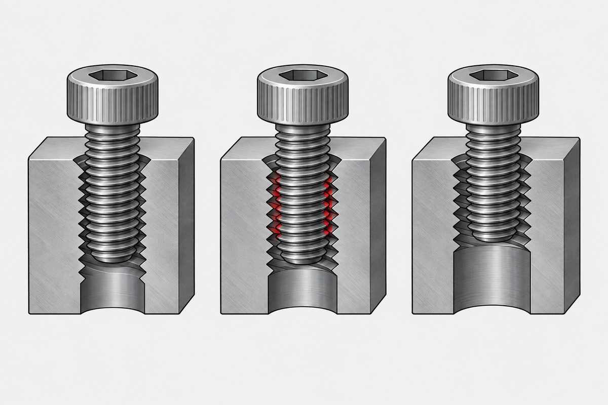
What the standard actually tabulates
Drill sizes for tapping have their own International Standard, ISO 2306, published in 1972 by the small tools committee and still current after a review in 2022. Its scope gives the rule of thumb in one clause: the drill diameter is approximately the nominal diameter of the thread minus the pitch. M6×1 gets a 5,00 mm drill.
The table is more interesting than the rule. Each row carries the maximum minor diameter for classes 5H, 6H and 7H, a minimum minor diameter, and only then a drill. The drill is the practical pick at the end of a tolerance, not the specification itself.
| Thread | Minor dia. min | Minor dia. max, 6H | Drill |
|---|---|---|---|
| M3 × 0,5 | 2,459 | 2,599 | 2,50 |
| M4 × 0,7 | 3,242 | 3,422 | 3,30 |
| M5 × 0,8 | 4,134 | 4,334 | 4,20 |
| M6 × 1 | 4,917 | 5,153 | 5,00 |
| M8 × 1,25 | 6,647 | 6,912 | 6,80 |
| M10 × 1,5 | 8,376 | 8,676 | 8,50 |
| M12 × 1,75 | 10,106 | 10,441 | 10,20 |
So an M6 hole is not 5,00 mm. It is anything from 4,917 to 5,153 mm for a 6H thread, a band nearly a quarter of a millimetre wide, and 5,00 is one point inside it. What the letter and the number in 6H each control is thread tolerance classes.
The standard says which way to lean, and it is not the instinctive one
From the introduction to ISO 2306, in its own words: the larger the drilled hole, within the relevant minor diameter tolerance, the more economical tapping becomes and the risk of tap breakage is reduced.
Read that against the reflex, which is that a smaller hole means more thread and more thread means a stronger joint. The standard is not arguing about strength. It is saying that once you are inside the tolerance, the whole band produces a conforming thread, and the top of it costs less to cut and breaks fewer taps.
That is a defensible trade because of where the joint usually fails. The design target is for the screw to break before the female thread strips, and how much engagement length that takes is thread engagement, with the published rules for it disagreeing among themselves in the engagement rules disagree. Length is the variable you have. Squeezing the last few hundredths out of the minor diameter is not.
The percentage, which is not in the standard at all
Shop charts quote a percentage of thread, usually 75%. ISO does not use percentages anywhere in this. The convention comes from the trade, and it measures depth against a sharp V thread, the un-truncated triangle, using % = 76,98 × (D − hole) ÷ P for metric threads.
The ISO basic profile truncates that triangle. The internal thread's basic minor diameter sits at D − 1,0825 P, while the sharp V root would be at D − 1,299 P. The ratio between them is 5/6, and it does not depend on the size.
So 83% is the ceiling for every conforming metric thread. Convert the M6×1 row and the 6H band runs from about 83% at the minimum minor diameter down to 65% at the maximum, with the ISO 2306 drill landing at 77%. A chart offering “100% thread” is offering a 4,70 mm hole, which is below the minimum minor diameter. That is not an aggressive choice. It is a thread that fails gauging.
M8×1,25 gives the same shape: 83% at 6,647 mm, 67% at 6,912, and the 6,80 mm drill at 74%. The number moves, the ceiling does not.
Two reasons the drill is not the hole
The first sentence of ISO 2306 is a list of everything that moves the produced diameter away from the drill's marked size: how accurately the drill point is ground, the material, the lubricant, and the alignment, feed and speed of the operation. A chart cannot know any of those, which is why the standard calls its own tables a guide.
The second is stranger and worth carrying around. When tapping relatively soft material the metal tends to be squeezed down towards the root, and the minor diameter of the tapped hole may come out smaller than the drill that made it. The standard adds that the tendency is much weaker in harder material and sometimes absent entirely.
That is the explanation for a familiar afternoon: the correct drill, a plug gauge that will not enter, and an aluminium part. The hole was right when it was drilled. It is the tapping that moved it, and moving to the larger end of the band is the response the standard already recommended for a different reason.
None of this applies to a screw that makes its own thread. For self-tapping and thread-forming screws the hole is set by a torque window rather than by a minor diameter, which is pilot hole sizing, and for trilobular thread-forming specifically, the hole is the variable.
Why the numbers on the chart are round
The drill column is not the middle of the band, and it is not a calculation. It is the nearest useful size from the standard twist drill series, which ISO 2306 says it took from ISO/R 235 for every size except four marked with an asterisk. The introduction then adds that users may reasonably choose their own diameters for particular applications, but that stocked diameters should be used whenever possible.
That is worth saying to anyone who has just calculated 5,03 mm and gone looking for a drill. The chart already made the same compromise. It landed on 5,00 because 5,00 exists, and because the standard would rather you were slightly high in the band than exactly on a number you cannot buy.
What to settle before the hole goes on the drawing
- Put the thread class on the drawing, not the drill. The hole that matters is the minor diameter after tapping, and 6H says what that band is. A drill size on a drawing is a process instruction that will be wrong for somebody's material.
- Decide which end of the band you want, deliberately. The standard recommends the larger end for tapping cost and tap life. If you want the smaller end, that should be a decision with a reason attached rather than a habit.
- Say what the material is. Soft alloys can close the minor diameter during tapping; hard ones will not.
- Drop the percentage, or state which convention it is. It is not an ISO quantity, and above 83% it describes a thread that cannot pass a gauge.
- Say whether anything else is threaded around it. If a second thread runs on the outside of the same wall, what is left is set by the external thread’s minor diameter and the internal thread’s major diameter, and at coarse pitch that runs out sooner than the two nominal sizes suggest.
This page covers step 2, the thread. The whole order is substrate, thread, head, drive, finish, documentation, and why doing it out of order is rework rather than a tweak is in specifying a screw.
Common questions
What drill size do I use for an M6 thread?
ISO 2306 names 5,00 mm, and its rule is that the drill is approximately the nominal diameter minus the pitch. The more useful answer is that for a 6H thread the minor diameter may be anywhere from 4,917 to 5,153 mm, and 5,00 mm is one point inside that band chosen because it is a stocked drill size. Which point you aim for is a decision the chart makes silently on your behalf.
Is a smaller tap drill stronger?
It puts more material in the thread, but ISO 2306 recommends the opposite bias, saying that the larger the drilled hole within the minor diameter tolerance, the more economical tapping becomes and the lower the risk of tap breakage. The design target is that the screw fails before the female thread strips, and the variable that buys that is engagement length rather than the last few hundredths of minor diameter. We found no published measurement quantifying the strength lost across the band, so no figure is given here.
Why do tap drill charts disagree with each other?
Because they are compressing a tolerance into one number and they do not all pick the same point in it, and because many of them are built from a percentage of thread convention rather than from the minor diameter limits. The percentage is a trade convention measured against a sharp V thread; ISO does not use percentages for this at all.
Can I really not get 100% thread engagement?
Not on the common convention, and not because of the tap. That convention measures depth against the sharp V triangle, while the ISO basic profile truncates the internal thread at a minor diameter of D minus 1,0825 P. The ratio between the two is 5/6, so 83% is the ceiling for any conforming thread at any size. A hole cut to 100% on that scale is below the minimum minor diameter and the thread will not gauge.
My hole measured correct before tapping and the gauge will not enter. What happened?
If the part is a soft alloy, ISO 2306 describes the mechanism in its introduction: the material tends to be squeezed towards the root during tapping, so the minor diameter of the tapped hole can end up smaller than the drill that produced it. The standard notes the tendency is much weaker in harder materials and sometimes absent. Moving to the larger end of the minor diameter band is the usual response, and it is the same direction the standard recommends for tap life.
References
- ISO 2306:1972 — drills for use prior to tapping screw threads; introduction, clause 1 scope, and Table 1 minor diameter limits and drill diameters for the coarse pitch series
- ISO 965-1 — ISO general purpose metric screw threads, tolerances, principles and basic data
- ISO 68-1 — ISO general purpose screw threads, basic profile, metric threads (the source of the 5H/8 truncation)
- ISO 235 — parallel shank twist drills and Morse taper shank twist drills, the series ISO 2306 selects its drill diameters from
ISO 2306:1972 was read from the publicly available preview PDF, which for a standard of that vintage carries the introduction, the scope and Table 1 in full; every dimension quoted here is from that table. The percentage arithmetic is our own, worked from the ISO 68-1 basic profile and checked against ISO 2306 Table 1: D minus 1,0825 P gives 4,9175 mm at M6 x 1 against the 4,917 mm the table prints. The 76,98 constant and the practice of quoting a percentage of thread are trade conventions; we did not trace them to a standards document and they should not be attributed to ISO. The ISO 965-1, ISO 68-1 and ISO 235 catalogue numbers were not cross-checked against a second source. Table 1 covers the coarse pitch series; the fine pitch series is Table 2 of the same standard and its numbers are not reproduced here.
Enquiries
If a tapped hole is part of the enquiry, send the thread class and the parent material rather than the drill size. The band is what has to be met, and in soft alloys the tapping moves the hole after the drill has left.
Request a quotation
Tell us the part and the quantity. We will come back on feasibility, lead time and price.
Or email us directly sales@tigerfasteners.com