 TIGERFASTENERS
A Thread Inside a Bolt Leaves Less Wall Than the Diameters Suggest
Someone posted a small stainless part with an M8 thread on the outside and an M6 thread on the inside and said it left about half a millimetre of wall. Two hundred and forty one points, a hundred and seventeen replies. Whether it can be machined is not ours to say. What is ours is the subtraction, because both boundaries are published numbers in a free preview of one ISO table. The answer is 0,233 millimetres, only one of the two pitches changes it, and the same table gave a different answer before 2023.
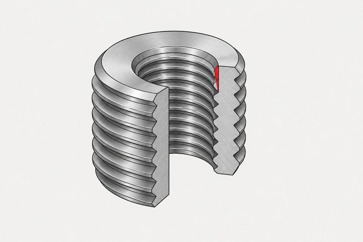
ISO 724:2023 gives the minor diameter of an external thread as d3 = d − 1,226 869 P. For M8 × 1,25 that is 6,466 mm. A tapped M6 hole cuts out to its own major diameter, 6,000 mm. What is left between them is (6,466 − 6,000) ÷ 2 = 0,233 mm of wall on each side.
ISO writes decimals with a comma, and this page keeps that. Every figure below is either read off a published table or is one subtraction of two published figures, and we say which each time.
The part in the post
On a mechanical engineering forum, two hundred and forty one points and a hundred and seventeen replies, someone asked whether two small stainless parts could be machined. The description is short and precise: the bolt has an M8 external thread and an M6 internal thread, “which leaves only around 0.5-0.6 mm of wall thickness between the threads”, and the complete assembly has to fit inside an 11 mm diameter and 15 mm length. Could it be made, and would it hold up to hand tightening.
We are not answering either of those. This page gives no machining advice, no strength opinion, no view on whether that part should exist, and it names no tool, material supplier or manufacturer. We read the post and not its replies.
What is answerable is the number in the middle of the sentence. The wall between two coaxial threads is a subtraction between two surfaces, and both of those surfaces have published diameters.
Which two surfaces
Going outward from the axis, the last material you meet is the root of the external thread. Going inward from the outside, the first place the material stops is the root of the internal thread. So the wall is bounded by two roots, and roots are where the standard puts its two least memorable symbols.
- Outside boundary: d3, the minor diameter of the external thread. For M8 × 1,25 the table gives 6,466
- Inside boundary: D, the major diameter of the internal thread, which is the nominal size. For M6 that is 6,000
The trap sits on the inside boundary. It is easy to reach for the tapped hole’s minor diameter instead, D1, which for M6 × 1 is 4,917, because that is the number near the tap drill. Subtract that one and you get (6,466 − 4,917) ÷ 2 = 0,775 mm, which is 3,3 times the real figure. The tap does not stop at its own minor diameter. It cuts out to the major diameter, and that is where your wall ends.
There is one more measurement worth naming because of where it lands. From the outer thread’s pitch diameter, 7,188 for M8 × 1,25, to the inner thread’s major diameter gives 0,594 mm, which falls inside the 0.5 to 0.6 the post reports. We have no way of knowing how the number in the post was obtained and we are not saying that is what happened. We mention it only because a pitch cylinder is a plausible thing to land on, and because it shows how far apart three defensible looking measurements of the same wall can be.
Which diameter belongs to which thread is worth having straight before any of this. That is covered on the page about the tap drill table, and is not repeated here.
Only one of the two pitches moves it
Keep the M6 hole and change the outer pitch. The d3 column of the same table does the work.
M8 × 1,25, d3 = 6,466 → wall
0,233 mm
M8 × 1, d3 = 6,773 → wall
0,387 mm
M8 × 0,75, d3 = 7,080 → wall
0,540 mm
Those three subtractions are ours. The three d3 values are the table’s.
Going from the coarse pitch to the finest one listed for M8 gives 2,32 times the wall. Now change the inner pitch instead, from M6 × 1 to M6 × 0,75. The wall does not move at all, because the internal thread’s major diameter is 6,000 either way. The tap cuts to the nominal size whatever its pitch.
Written out from the standard’s own formula, and this rearrangement is ours:
wall per side = (d − D) ÷ 2 − 0,613 435 × P, where d is the outer nominal, D is the inner nominal, and P is the outer pitch only. The inner pitch does not appear.
And it runs out at M12
Take the same arrangement up the sizes, always with coarse pitch outside and a nominal two millimetres smaller inside. Every wall figure below is one subtraction of two numbers from the table.
- M6 × 1 outside, M4 inside: (4,773 − 4,000) ÷ 2 = 0,387 mm
- M8 × 1,25 outside, M6 inside: (6,466 − 6,000) ÷ 2 = 0,233 mm
- M10 × 1,5 outside, M8 inside: (8,160 − 8,000) ÷ 2 = 0,080 mm
- M12 × 1,75 outside, M10 inside: (9,853 − 10,000) ÷ 2 = −0,074 mm
The gap between the two nominal diameters is one millimetre per side in every row. What changes is the pitch, and the pitch is what eats the wall. By M12 coarse the external thread’s root diameter, 9,853, has gone inside the tapped hole’s major diameter of 10,000. On the design profile there is no wall left to be thin.
That is not a manufacturing verdict, and it is not a claim that no hollow M12 exists. It is a statement about one geometry, coarse pitch outside and two millimetres smaller inside, and where that geometry stops closing.
The number changed in 2023
Here is the part that would catch anyone working from an older copy. Until the third edition, the same table gave a different answer.
ISO 724:1993 had one minor diameter column, headed D1, d1. One number, serving both threads. Its clause 5 gives the formulae, and the last of them reads d1 = d − 2 × (5/8) H = d − 1,082 5P, the same depth as the internal thread.
The 2023 edition splits that column in two and labels the halves. Internal thread, flat crest, D1. External thread, rounded root, d3. And the foreword lists the change plainly: three symbols d3, H1 and h3 have been added to the symbols clause, and “the values and formula for the minor diameter of external thread, d3, have been added in Table 1 and Clause 5”. The word basic profile in the scope became design profile at the same time.
So run the four rows again on the 1993 number. Ours, from published values:
M6 / M4: 0,459 M8 / M6: 0,323 M10 / M8: 0,188 M12 / M10: +0,053
Against the 2023 values of 0,387, 0,233, 0,080 and −0,074.
The M12 case exists on the old table and does not exist on the new one. Same nominal sizes, same pitches, same standard number, different edition. And the gap is not random: the old figure is larger by exactly 0,072 168 × P per side, which is 0,090 mm at M8 coarse and 0,127 mm at M12 coarse. The coarser the thread, the further out the old number puts you. At M10 it is 2,35 times the wall you actually have.
Why the two depths differ at all is in the fractions. The internal thread goes to 5/8 of the fundamental triangle and the external thread on the design profile goes to 17/24. The ratio is 17/15 exactly, which is our arithmetic on the standard’s coefficients: 1,226 869 ÷ 1,082 532 = 1,133 3.
These are basic dimensions, not limits
Everything above is the design profile. A real thread is made to a tolerance class, and the tolerance is where the last surprise sits.
ISO 965-1:1998 carries the table of fundamental deviations. Its two headings read internal thread D2, D1 and external thread d, d2. Tolerance position H has a deviation of zero at every pitch in the table, and so does position h. Position g is −28 µm at a pitch of 1,25, and −34 at 1,75.
Now read those two headings against the two diameters that bound our wall. Neither d3 nor D appears in either heading. That is an observation about what that table lists, not a claim that those two diameters are untoleranced. Where their limits come from is elsewhere in a document whose free preview ends before we get there, and this page does not guess at it.
Which is the honest shape of the whole answer. 0,233 mm is what the design profile leaves. It is a ceiling for planning and a floor for nothing. A part made to a real tolerance class is not obliged to have exactly that, and the direction the classes push is a question for the clauses we did not read.
What to take from it
- The wall is bounded by two roots, the external thread’s minor diameter and the internal thread’s major diameter, which is the nominal size
- Measuring to the tap drill instead gives about three times too much. For M8 over M6 that is 0,775 mm against 0,233 mm
- Only the outer pitch changes the wall. Changing the inner thread from M6 × 1 to M6 × 0,75 moves it not at all
- wall = (d − D) ÷ 2 − 0,613 435 P, with P the outer pitch, which is our rearrangement of the standard’s own formula
- Coarse pitch outside with two millimetres smaller inside runs out between M10 and M12, going 0,387, 0,233, 0,080 and then negative
- ISO 724 gave a different external minor diameter before 2023. The 1993 table had one column for both threads at d − 1,082 5P; the 2023 table adds d3 at d − 1,226 869 P
- The old number overstates the wall by 0,072 168 P per side, so the error grows with the pitch
- All of it is the design profile. Tolerance classes are a separate question and the free preview of ISO 965-1 does not settle it
The question in the post was whether the part is possible. That still belongs to whoever has to cut it. What the table settles is a smaller thing worth settling first: before anyone argues about feasibility, everyone should be arguing about the same number, and three reasonable people can pick three different ones off the same drawing.
This page covers step 2, the thread. The whole order is substrate, thread, head, drive, finish, documentation, and why doing it out of order is rework rather than a tweak is in specifying a screw.
Common questions
How much wall is left between an M8 external thread and an M6 internal thread?
On the design profile, 0,233 mm per side. ISO 724:2023 gives the minor diameter of an M8 × 1,25 external thread as 6,466 mm and the internal thread of an M6 cuts out to its major diameter of 6,000 mm. Half the difference is 0,233 mm. That is basic dimensions, not a limit for a toleranced part.
Why do I get a bigger number when I work it out myself?
Usually because of which inner boundary you subtract. The tapped hole’s minor diameter for M6 × 1 is 4,917 mm and gives 0,775 mm, about three times too much, but the tap does not stop there. Measuring from the outer thread’s pitch diameter of 7,188 mm gives 0,594 mm. The material actually ends at the internal thread’s major diameter.
Does a finer thread on the inside give me more wall?
No. The internal thread’s major diameter is the nominal size whatever the pitch, so M6 × 0,75 and M6 × 1 leave exactly the same wall. Only the outer thread’s pitch changes it: M8 × 1,25, M8 × 1 and M8 × 0,75 give 0,233, 0,387 and 0,540 mm.
Is there a formula?
Rearranging the standard’s own d3 formula gives wall per side = (d − D)/2 − 0,613 435 × P, where d is the outer nominal diameter, D is the inner nominal diameter and P is the outer pitch. The inner pitch does not appear in it. That rearrangement is ours; the coefficient is the standard’s.
At what size does this arrangement stop working?
With coarse pitch outside and a nominal two millimetres smaller inside, the walls run 0,387 mm at M6 over M4, 0,233 at M8 over M6, 0,080 at M10 over M8, and −0,074 at M12 over M10. At M12 the external thread’s root diameter of 9,853 mm has gone inside the tapped hole’s major diameter of 10,000 mm, so on the design profile there is nothing left.
Did ISO 724 change?
Yes. The 1993 edition had a single minor diameter column headed D1, d1, with d1 = d − 1,082 5P, the same depth for both threads. The 2023 third edition splits it into D1 for the internal thread at a flat crest and d3 for the external thread at a rounded root, with d3 = d − 1,226 869 P. The foreword says the values and formula for d3 were added in Table 1 and Clause 5.
How much difference does that make?
The old figure overstates the wall by 0,072 168 × P per side, which is our arithmetic on the two coefficients. That is 0,090 mm at M8 coarse and 0,127 mm at M12 coarse. The M8 over M6 case goes from 0,323 mm on the 1993 numbers to 0,233 mm on the 2023 numbers, and the M12 over M10 case goes from just possible to not possible.
Do tolerances make it better or worse?
This page does not say, because the free preview of ISO 965-1:1998 ends before the clauses that would answer it. What we can report is that its table of fundamental deviations is headed D2, D1 for internal threads and d, d2 for external threads, and neither of the two diameters that bound this wall is in those headings. Their limits are specified elsewhere in that document.
Can the part in the forum post be machined?
This page does not answer that and does not try. It gives no machining or strength advice, comments on no specific part, and names no tool or supplier. What it establishes is which two published numbers set the wall, so that a discussion about feasibility can at least start from the same figure.
References
- ISO 724:2023, ISO general purpose metric screw threads, Basic dimensions. Third edition, April 2023, free ten page preview with Table 1
- ISO 724:1993, second edition, free nine page preview with clause 5 and Table 1
- ISO 965-1:1998, tolerances for metric screw threads, free eleven page preview reaching the table of fundamental deviations
- r/MechanicalEngineering, where a part with a thread inside a thread raised the question of how much wall is left
Three free previews were downloaded and read: ISO 724:2023 (catalogue 85104, ten pages, Table 1 visible in full), ISO 724:1993 (catalogue 4958, nine pages, clause 5 and Table 1 visible) and ISO 965-1:1998 (catalogue 5393, eleven pages, reaching printed page 9). Every figure quoted from those tables was checked against a rendered image of the page rather than extracted text, because the older scan reproduces subscripts badly. The following are our own arithmetic, not statements by any of the documents: that the wall is bounded by the external thread’s minor diameter and the internal thread’s major diameter; every wall figure on this page, each of which is half the difference between two published diameters; the rearranged formula (d − D)/2 − 0,613 435 P; the observation that the inner pitch does not enter it; the ratio 2,32 between the coarse and finest M8 walls; the per side overstatement of 0,072 168 P between the two editions and the factors 1,39 at M8 and 2,35 at M10; and the ratio 17/15 between the two thread depths. All of it is the design profile. A real thread is made to a tolerance class and this page does not say which way that moves the wall, because the free preview of ISO 965-1 ends before the clauses that would answer it; what it does show is that the fundamental deviation table is headed D2, D1 for internal threads and d, d2 for external threads, and neither diameter that bounds this wall is in those headings, which is an observation about that table and not a claim that they are untoleranced. ISO 68-1 has not been read, so nothing here describes the radius of the rounded root or the shape of a rolled thread root, and ISO 261 and ISO 5408 have not been read either. We give no machining advice, no strength opinion and no view on whether the part in the forum post should be made, and we name no tool, material or manufacturer. We do not know how the wall figure in that post was obtained and the pitch diameter measurement mentioned above is offered as an illustration, not as an explanation of it. We read the forum post and not its replies, and no forum username appears on this page. Which diameter belongs to which thread is covered on an earlier page and is not repeated here.
Enquiries
If a drawing puts one thread inside another, the number worth agreeing on before anything else is which two diameters you are subtracting. Send us the nominal sizes and both pitches and we will tell you what the design profile leaves, and what we would need from you about tolerance class before saying anything further.
Request a quotation
Tell us the part and the quantity. We will come back on feasibility, lead time and price.
Or email us directly sales@tigerfasteners.com