 TIGERFASTENERS
The compatibility table everyone cites, and the standard it does not come from
Search for whether you may put a stainless screw into an aluminium bracket and you will find the same table on twenty sites — an “anodic index” for each metal, subtract one from the other, keep the difference under 0.15 V outdoors, 0.25 V indoors, 0.50 V in a controlled room. Nearly every copy credits MIL-STD-889. We went and read MIL-STD-889.
What MIL-STD-889 actually contains
The current edition is MIL-STD-889D, 21 July 2021, Galvanic Compatibility of Electrically Conductive Materials. Notice 1 of 29 April 2026 confirmed it remains valid for acquisition. It superseded 889C (2016), which superseded 889B (1976, with notices through 1993).
Across the editions that can be read in full:
- 889B — Table I is a matrix of material groups and protective systems. Table II is a galvanic series of selected metals in seawater, ordered active to noble, with no numbers attached.
- 889C — clause 3.3 sends you to Table I for relative compatibility. Table II is the seawater galvanic series, sourced to an Army Missile Command report. Table B-I gives standard electrode potentials of pure metals, which is a different thing again.
- 889D — Tables I to III give the anodic corrosion rate at a 1:1 area ratio in artificial seawater, graded 0 to 6. Grade 0 is under 0.009 mil/year and is the definition of compatible.
None of them contains a table called Anodic Index, and none of them contains the 0.15/0.25/0.50 V rule. 889D goes further: clause 3.10 says its Table IV galvanic series is for reference only and shall not be used to determine galvanic compatibility, and the foreword says the older potential-difference approach omits kinetics and is not a corrosion-rate indicator.
The first and A editions are not available to us in reliable full text, so the honest statement is narrower than the internet's: in the editions that can be checked, the table is not there, and no original page has turned up that supports the attribution.
Where the table does come from
MIL-F-14072D (ER), 4 October 1990 — a finishes specification for ground electronic equipment. Its Table VI, “Compatible couples”, has a column headed literally “Anodic Index (0.01 V)”, alongside the EMF versus a saturated calomel electrode, the material groups, and the permissible couples. Gold's group sits at EMF +0.15 V and index 0; magnesium at −1.60 V and index 175.
The same method appears in connector specifications — MIL-DTL-26482H and MIL-DTL-28754E both use a derived anodic index with a 0.25 V maximum difference. NASA-STD-6012A carries its own modified version, in which all conductive carbon becomes Group 0 and magnesium lands at 190 rather than 175, so NASA is not the source of the common table either.
The index is a derived scale, not a material property. Someone took a seawater galvanic series measured at room temperature against SCE, grouped it, discretised it in units of 0.01 V, and shifted the zero to gold. The widely copied version has dropped the electrolyte and the reference electrode. That does not mean the original had no conditions. It means the copies lost them.
The three thresholds trace to one place, and it cites the wrong standard
The complete harsh/normal/controlled rule at 0.15, 0.25 and 0.50 V can be located in ANSI/SCTE 129-2007, clause 2.3.5, a cable-industry standard. That document states the three thresholds and attributes them to MIL-STD-889. The attribution is wrong, and the rule appears to have propagated from there.
An earlier authoritative origin for the set of three could not be found. The 0.25 V figure alone does have military backing, in MIL-F-14072D clause 3.13 and the connector specifications above — but those are specific to ground electronic equipment and connectors, and the number does not survive being lifted out of that scope.
NASA's own rule is stricter and conditional: potential difference not to exceed 0.25 V, unless the measured couple current density is at or below 1 µA/cm² with no pitting, with the test area ratio matching the actual design. That last clause is the interesting one, and it is the part the popular table has no way to express.
Why a voltage threshold cannot answer the question on its own
The potential difference tells you the driving tendency — which metal will be attacked, and how hard the cell is being pushed. It does not tell you the rate, because the rate depends on polarisation behaviour, the electrolyte's conductivity, the wetted area ratio, the passive state of anything that has a passive state, oxygen access, temperature and time of wetness.
Area ratio is the one with the clearest arithmetic. Current is conserved between the electrodes, so I = Aaia = Ac|ic|, and where the reaction is cathodically controlled with negligible polarisation, ia ≈ |ic| Ac/Aa. MIL-STD-889D Appendix C clause C.2.8 is specific: under cathodic control, increasing cathode area by two to three times typically increases the current by the same factor — but under mixed control the relationship is not proportional, and under anodic control the cathode area matters little.
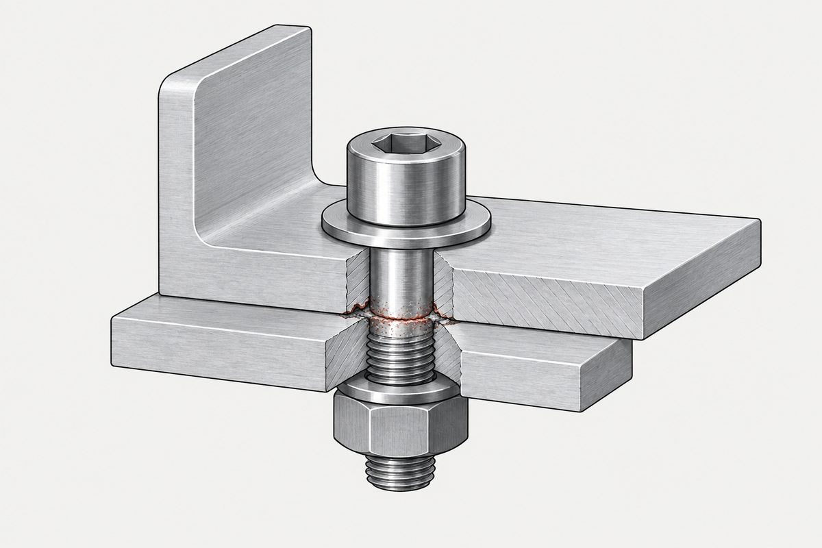
So a large cathode with a small anode is the dangerous geometry, and that is why a small aluminium screw into a large stainless plate is a worse arrangement than a small stainless screw into a large aluminium plate. 889B and 889C say as much directly, recommending that small bolts be of the same or a more noble material. The mechanism is worked through in stainless screws into aluminium.
Stainless does not occupy one position on the series
Typical corrosion potentials in flowing seawater against SCE:
| Material / state | V vs SCE |
|---|---|
| Magnesium and its alloys | −1.60 to −1.63 |
| Zinc | −0.98 to −1.03 |
| Aluminium alloys | −0.76 to −1.00 |
| Carbon steel, cast iron | −0.60 to −0.72 |
| 304 stainless, active | −0.44 to −0.58 |
| 316/317 stainless, active | −0.33 to −0.46 |
| 304 stainless, passive | −0.04 to −0.10 |
| 316/317 stainless, passive | 0.00 to −0.10 |
| Titanium | +0.04 to +0.06 |
| Graphite | +0.20 to +0.30 |
Stainless appears twice, and the gap between its two entries is on the order of several hundred millivolts — roughly 0.44 V for 304 and 0.35 V for 316 taking range midpoints. Active 304 is adjacent to carbon steel and can overlap it at the edges. In shielded, low-flow or poorly aerated chloride environments, these grades can shift towards about −0.5 V vs SCE.
What this changes is the kind of risk, not simply its direction. A stainless screw still avoids making the fastener the small anode. If it depassivates in a chloride-bearing crevice, the exposure moves to the screw's own pitting, crevice corrosion or cracking — and depassivation can also narrow the driving difference against aluminium. Both the substrate's galvanic exposure and the fastener's local corrosion have to be checked; neither one substitutes for the other.
Why stainless has a passive film at all, and what removes it, is in A2 and A4 are not grades of “better”.
Taiwan is not a “normal” environment
If you are picking a threshold row off the table, the row you pick assumes something about where the part lives. For work built or installed in Taiwan, that assumption usually needs to be harsher than it looks.
A one-year exposure programme at the Port of Taichung classified carbon steel, zinc, copper and aluminium all as C4 under ISO 9223. The Ministry of Transportation's Institute of Transportation described the island in a 2024 report as hot, humid and salt-laden, with higher chloride deposition along the northern and western coasts in autumn and winter. An earlier 23-station study found most sites highly corrosive to zinc.
- Coastal sites, port areas, windward faces, rooftops, semi-outdoor cabinets and anywhere air conditioning condenses should be treated as salt-and-humidity exposure.
- “Indoors” is not the same as controlled. An undehumidified warehouse, a basement or a sealed equipment cabinet can spend long periods at condensing humidity.
- Salt deposited in dry weather stays there and re-wets into a conductive film at the next humid spell.
Storage is its own problem for fresh zinc — see white rust is a storage problem.
What to do instead of looking up a number
- Break one of the three conditions. Galvanic corrosion needs electrical contact, a shared electrolyte and a closed current path, all at once. Insulating washers and sleeves, sealing, drainage and wet-installed joints attack the problem more directly than hunting for a compatible pair.
- Coat both sides, or the cathode. Coating only the anode is a trap: a small break in that coating becomes a very small anode against an unchanged large cathode. 889D clause 5.4 recommends coating both, or a sacrificial treatment on the cathode.
- Get the geometry right before the chemistry. A more noble small fastener is often the correct design, not a mistake.
- Do not forget the non-metals. Graphite and carbon-fibre composites are strong cathodes. CFRP against aluminium is a common version of this problem with no metal on one side.
- Check for the non-galvanic prohibitions. 889D Appendix A clause A.4.7 warns of metal-induced embrittlement between titanium and cadmium, zinc or silver. A compatibility table by potential will never show you that.
- Test if it matters. ASTM G71 covers conducting and evaluating galvanic corrosion tests in electrolytes, which is the route to an actual number for your actual pair.
And note what “compatible” claims. 889D clause 5.1 warns that it means low galvanic corrosion under the specified conditions. It says nothing about pitting, crevice corrosion or stress corrosion cracking.
Where this connects
The mechanism and the area-ratio argument in full are in stainless screws into aluminium. What a plated barrier buys you and how long it lasts is in choosing a finish, and the two stainless grades people treat as a ladder are in A2 and A4.
References
- MIL-STD-889D, 21 July 2021, Galvanic Compatibility of Electrically Conductive Materials — §§1.1–1.3, 3.10, 5.1, 5.3–5.5, Tables I–IV, Appendix A §A.4.7, Appendix C §§C.2.7–C.2.12; Notice 1, 29 April 2026 (validation)
- MIL-STD-889C (2016) §3.3, Tables I, II, B-I; MIL-STD-889B (1976) Tables I–II
- MIL-F-14072D (ER), 4 October 1990 — §3.13 and Table VI, “Compatible couples”, column “Anodic Index (0.01 V)”
- MIL-DTL-26482H §6.6/Table XXXI; MIL-DTL-28754E §6.5/Table VI — derived anodic index, 0.25 V maximum
- NASA-STD-6012A — Table 1 (modified anodic index) and §4.9.4a
- ANSI/SCTE 129-2007 §2.3.5 — the 0.15/0.25/0.50 V rule, with its attribution to MIL-STD-889
- ASTM G82-98(2021)e1 — developing and using a galvanic series for prediction; ASTM G71-81(2024) — conducting and evaluating galvanic corrosion tests in electrolytes
- ISO 16364:2026 — guidelines for galvanic corrosion control; ISO 7441:2015; ISO 9223:2012
- Lo and Lin, 2018, Materials and Corrosion — Port of Taichung one-year exposure, ISO 9223 C4; Corrosion Science 48 (2006) — 23-station Taiwan study; Institute of Transportation, MOTC, 2024
- Australasian Corrosion Association — seawater galvanic series potentials
Acceptance for any particular assembly is governed by your drawing and your own testing.
On the fastener side of the same question, the structural bolting specification offers a weathering type, and says that if the type is not specified either may be supplied.
One standard turns the dissimilar metal problem into a design feature: a stud may be two materials friction welded together so that the end which becomes weld matches the parent metal.
This page covers step 1, the substrate. The whole order is substrate, thread, head, drive, finish, documentation, and why doing it out of order is rework rather than a tweak is in specifying a screw.
Common questions
Is the anodic index table from MIL-STD-889?
No. In MIL-STD-889B, 889C and 889D, which can be read in full, there is no table called Anodic Index. Those editions use material-group compatibility matrices, a seawater galvanic series without numbers, and in the 2021 edition a matrix of anodic corrosion rates. The table with an index for each metal is traceable to MIL-F-14072D of 1990, a finishes specification for ground electronic equipment, whose Table VI carries a column headed Anodic Index in units of 0.01 volts.
Where does the 0.15, 0.25 and 0.50 volt rule come from?
The complete three-level rule can be located in ANSI/SCTE 129-2007 clause 2.3.5, which states it and attributes it to MIL-STD-889. That attribution is not supported by the text of MIL-STD-889 in any edition we could check. No earlier authoritative source for the set of three could be found. The 0.25 volt figure on its own does appear in MIL-F-14072D and in connector specifications, but those apply to ground electronic equipment and connectors.
What does the current MIL-STD-889 use instead of a voltage difference?
MIL-STD-889D grades pairs by the anodic corrosion rate measured at a one-to-one area ratio in artificial seawater, from grade 0 at under 0.009 mil per year, which is the definition of compatible, up to grade 6 above 100 mil per year. Its foreword states that the older potential-difference approach omits kinetics and is not a corrosion rate indicator, and clause 3.10 says its own galvanic series table is for reference only and must not be used to determine compatibility.
Why does stainless steel appear twice on a galvanic series?
Because its position depends on whether the passive film is intact. Passive 304 sits near minus 0.04 to minus 0.10 volts against a saturated calomel electrode in seawater, while active 304 sits near minus 0.44 to minus 0.58, adjacent to carbon steel. The gap is on the order of several hundred millivolts. In shielded, low-flow or poorly aerated chloride environments these grades can shift towards about minus 0.5 volts.
Does an area ratio matter more than the potential difference?
The potential difference indicates the driving tendency; the area ratio strongly affects the penetration rate where the reaction is cathodically controlled. MIL-STD-889D Appendix C states that under cathodic control with negligible polarisation, increasing cathode area two to three times typically increases the current by the same factor, while under mixed control the relationship is not proportional and under anodic control cathode area matters little. A large cathode with a small anode is the dangerous geometry.
Should a fastener be more noble or less noble than the parts it joins?
Usually more noble, because the fastener is the smallest piece of metal in the joint and a small anode concentrates the attack. MIL-STD-889B and 889C recommend that small bolts be of the same or a more noble material. The trade is that a passive fastener in a chloride-bearing crevice can lose its passive film and suffer pitting or crevice corrosion of its own, so both the substrate exposure and the fastener exposure need checking.
Enquiries
If a joint puts two different metals together, tell us the mating material, the environment and whether the assembly is sealed when you send the screw. Those decide the finish, and the finish is usually the part that is cheapest to get right early.
Request a quotation
Tell us the part and the quantity. We will come back on feasibility, lead time and price.
Or email us directly sales@tigerfasteners.com