 TIGERFASTENERS
A Blind Rivet Has a Strength Class
A post on r/HVAC opens with a curse on anyone who uses rivets in residential sheet metal, written by somebody who had just spent a shift reaching into a 14 inch access to drill out fifteen of them. The top reply says the poster rivets filter cabinets on as far back as he can reach because all of his installs are permanent. Eighty-eight comments, and the argument is entirely about whether the joint comes apart again. Not one of them mentions that the thing they are drilling out is ordered by a designation with a strength class on the end of it.
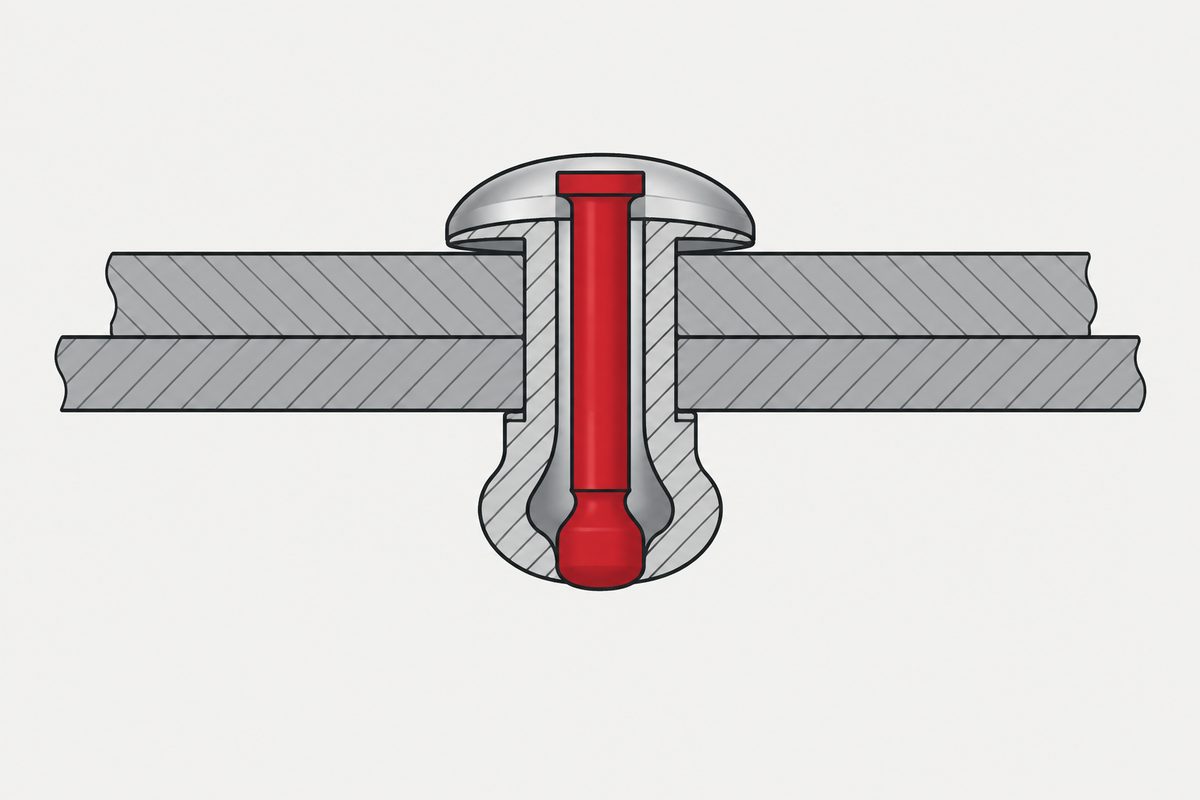
The designation for one of these is Blind rivet ISO 15977 − 4 × 12 − AlA/St − L, and the last letter is a strength class the same way 8.8 is a property class on a bolt. There are two, L and H, and at 6,4 mm they differ by more than a thousand newtons of shear. Almost nobody writes the letter, which means almost everybody takes L.
The standard is ISO 15977:2002, Open end blind rivets with break pull mandrel and protruding head, AlA/St. That title is a specification in itself: open end, a mandrel that pulls until it breaks, a head that stands proud, an aluminium alloy body and a steel mandrel, in nominal diameters from 2,4 mm up to and including 6,4 mm. Change any one of those and you are in a different standard in the same family, so everything below belongs to this one.
What the class letter buys
Clause 5 sets minimum shear and minimum tensile loads for two grades of rivet body. These are the rows we could read cleanly in the public preview:
| d nom | Class L shear / tensile | Class H shear / tensile | Mandrel break load, max |
|---|---|---|---|
| 2,4 mm | 250 N / 350 N | 350 N / 550 N | 2 000 N |
| 3 mm | 400 N / 550 N | 550 N / 850 N | — |
| 3,2 mm | 500 N / 700 N | 750 N / 1 100 N | — |
| 6 mm | 2 100 N / 3 000 N | 3 200 N / 4 600 N | 9 000 N |
| 6,4 mm | 2 200 N / 3 150 N | 3 400 N / 4 850 N | 11 000 N |
The 4, 4,8 and 5 mm rows sit under the preview watermark and we could not read them, so they are not reproduced. What the readable rows show is that the letter is worth real money in both directions: at 3,2 mm, H buys half again the shear of L, and at 6,4 mm it is a difference of 1 200 N. A drawing that names a diameter and a length has specified two of the four fields in the designation.
One number in that table is a ceiling
The last column reads maximum, not minimum, and that is not a typographical accident. The mandrel break load is the force at which the pin is supposed to snap, and the standard caps it rather than requiring it to be high. A mandrel that refuses to break is not a stronger rivet. It is a rivet that has not finished being installed, and the load goes into the tool and the joint instead of into forming the blind head.
This is the same reading problem as the prevailing torque figure on a locking nut, which is also a ceiling and gets added to things it should not be added to. When a specification gives a maximum, the question to ask is what goes wrong if the value is high, not what you gain.
Two very small numbers, and they are about the pin
Clause 6 says the load required to push the mandrel out shall exceed 10 N. Clause 7 sets a head retention test load that the remaining portion of the mandrel must survive without being ejected:
| d nom | 2,4 | 3 | 3,2 | 4 | 4,8 | 5 | 6 | 6,4 |
|---|---|---|---|---|---|---|---|---|
| Head retention load, N | 10 | 15 | 15 | 20 | 25 | 25 | 30 | 50 |
Put those beside the strength table and the scale is worth pausing on. A 6,4 mm rivet carries a minimum shear load of 2 200 N and its mandrel plug has to stay put against 50 N, which is about five kilograms. The joint strength and the does-the-pin-stay-in strength are two different numbers roughly forty times apart, and they answer different worries. If a loose mandrel rattling out into a blower wheel or a duct run is a problem for you, that is the second number, and it is small on purpose, because the pin is a leftover and not a load path you are entitled to count on.
The hole is part of the strength
Clause 3.3 tabulates the clearance hole, and the tolerance is tight enough to be surprising:
| Rivet d nom | Hole min | Hole max |
|---|---|---|
| 2,4 | 2,5 | 2,6 |
| 3 | 3,1 | 3,2 |
| 3,2 | 3,3 | 3,4 |
| 4 | 4,1 | 4,2 |
| 4,8 | 4,9 | 5,0 |
| 5 | 5,1 | 5,2 |
| 6 | 6,1 | 6,2 |
| 6,4 | 6,5 | 6,6 |
Every row is the same: nominal plus one tenth, to nominal plus two tenths. A whole millimetre band does not exist anywhere in that table. The standard then says what happens if you miss it, in its own words: non-conformance to those values may result in assembly difficulties and a reduction in the shear and tensile loads specified.
There is a second sentence that reads like it was written after watching somebody work. To help alignment, the hole may be enlarged beyond the table on the access side only, and doing so may also reduce the specified shear and tensile loads. So the field fix is allowed, it is bounded to one of the two sheets, and it is priced. A rivet fills its hole, which is why the hole belongs to the fastener’s rating rather than being clearance the way it is on a screw.
Grip range, where the two ends are not the same kind of limit
Table 1 lists a recommended grip range against each rivet length; the shortest rivet in it, nominal length 4 mm, is given as 0,5 to 2,0 mm of total sheet. Underneath the table is a footnote that is easy to skim past and worth reading twice. The minimum grip lengths, it says, are given as a recommendation only, and it may be possible in individual cases to go below the minimum values.
Nothing of the kind is said about the maximum, and the asymmetry is the useful part. Too thin and you are outside a recommendation. Too thick and the mandrel is breaking before the blind head has formed against anything, which is not a weaker joint so much as an unfinished one. This is the same asymmetry that catches people out on the two numbers printed on a box of self-drilling screws, where the drilling capacity and the clamping range answer different questions and only one of them is about how thick the stack can be.
Where those loads were measured, which is not in a duct
The numbers in the tables above are all qualified by the phrase when tested in accordance with ISO 14589, so it is worth knowing what that fixture looks like. ISO 14589:2000, Blind rivets, Mechanical testing specifies five tests: shear, tensile, mandrel head retention capability, mandrel push out resistance before setting, and mandrel break load, at an ambient temperature of 10 to 35 °C. Three of the five are about the mandrel, which tells you how much of the trouble with this fastener lives in the part you throw away.
The shear and tensile tests strain a rivet set in a fixture until it fails. The test plates are steel of hardness not less than 420 HV30. There are two fixtures for each method: a routine one, and a referee one whose inserts are hardened and tempered steel at 700 HV30 minimum, which is decisive in the case of dispute and takes new inserts for every referee programme. Plates are discarded once the holes stop being round.
So a published shear load is a property measured between two pieces of hard steel with a hole held to a tenth of a millimetre. Galvanised duct at less than a millimetre is not that. The number is not wrong, it is a fastener rating rather than a joint rating, and the joint can run out first. This is the same shape of mistake as reading a salt spray figure as a service life, where the panel is also not the part.
Which does not settle the argument in that thread
None of this says the person cursing at fifteen rivets in a return boot was wrong. Removal is destructive, it costs a shift, and that cost appears nowhere in ISO 15977, which has clauses for workmanship, for acceptance inspection under ISO 3269, and for checking a set rivet at 5 times magnification for cracks, and no clause at all for whether the next person can get it apart. Serviceability is a real requirement and it has to come from the drawing, because it will not come from the fastener standard.
What the standard does settle is the other half of the argument, the half nobody was having. A blind rivet is a specified fastener with a class, a rated shear load, a rated tensile load, a capped mandrel break load, a hole tolerance of a tenth of a millimetre and an acceptance procedure. Our own earlier page put it that a rivet gives you no clamp force you can set, and that remains true, because clamp force is the thing the squeeze happens to produce. It was never true that a rivet has no number.
And the alternative that thread wanted, a sheet metal screw in thin gauge, is the case where the rating genuinely does thin out, because what holds is the length of thread the sheet can engage. Both fasteners are specified. They are specified by different documents, for different quantities, and the choice between them is a choice about which one you intend to undo.
This is not one of the six steps. It shows up across them, or after assembly. Where the decisions that lead here were made is in specifying a screw, which sets out the order and why doing it out of order is rework.
Common questions
Do blind rivets have a strength rating?
Yes, and two of them. ISO 15977 sets a minimum shear load and a minimum tensile load for each diameter in two grades of rivet body, class L and class H, and the class letter is the last field of the designation. At 3,2 mm the readable figures are 500 N shear and 700 N tensile for L against 750 N and 1 100 N for H; at 6,4 mm they are 2 200 and 3 150 against 3 400 and 4 850. Those apply to the aluminium body and steel mandrel construction that standard covers.
What does the letter on the end of a rivet designation mean?
It is the strength class of the rivet body. A full designation under that standard reads like Blind rivet ISO 15977 - 4 x 12 - AlA/St - L, which is the standard number, the nominal diameter and length, the body and mandrel materials, and then the class. A purchase that names only diameter and length has left the last field open, and there is a substantial difference between the two classes.
Why is the mandrel break load a maximum rather than a minimum?
Because the pin is meant to break. Its job is to draw the body up until the blind head has formed and then let go, so a high break load is a fault rather than a strength. The standard caps it, at 2 000 N for a 2,4 mm rivet and 11 000 N for a 6,4 mm one in the readable rows. The same reading applies to any specification value given as a maximum: ask what goes wrong when it is high.
How much force keeps the mandrel from falling out?
Very little, and that is deliberate. The push-out load before setting only has to exceed 10 N, and the head retention test load for the portion left in a set rivet runs from 10 N at 2,4 mm to 50 N at 6,4 mm. A 6,4 mm rivet with a 2 200 N minimum shear load therefore holds its own leftover pin against about five kilograms. If a loose mandrel getting into machinery matters in your application, that is the number to look at, not the shear load.
What size hole should a blind rivet go into?
A tight one. The tabulated clearance hole is nominal plus 0,1 mm to nominal plus 0,2 mm across the whole range, so a 3,2 mm rivet wants 3,3 to 3,4 mm and a 4,8 mm rivet wants 4,9 to 5,0 mm. The standard states that departing from those values may cause assembly difficulty and reduce the specified shear and tensile loads, and that a hole enlarged to help alignment is permitted on the access side only, with the same warning attached.
Can I use a rivet outside its grip range?
The two ends are not the same kind of limit. The standard describes the minimum grip lengths as a recommendation only and says it may be possible in individual cases to go below them. It says nothing comparable about the maximum, and going over it means the mandrel breaks before the blind head has formed properly against the far sheet. Treat the top of the range as the real boundary and the bottom as guidance.
References
- ISO 15977:2002 — Open end blind rivets with break pull mandrel and protruding head, AlA/St. Clauses 3.3, 4, 5, 6, 7, 8, 9 and 10, and Tables 1 to 4
- ISO 14589:2000 — Blind rivets, mechanical testing. Scope and clause 3, the shear and tensile test fixtures
- r/HVAC — the thread this started in, eighty-eight comments on getting rivets back out again
Both standards were read from their publicly available previews and every clause and table reference above comes from that text. The catalogue numbers were confirmed separately on the ISO site, where both entries sit at stage 90.93, international standard confirmed. The 4, 4,8 and 5 mm rows of the mechanical properties table are obscured by the preview watermark and are deliberately not reproduced here, and for the same reason only the first grip range entry is quoted rather than the table. The ISO 14589 preview ends at page 5 of 13, so the shear and tensile fixtures are described and the procedures for the three mandrel tests are not. Every figure on this page belongs to the aluminium body with steel mandrel construction that ISO 15977 covers, and should not be carried across to steel or stainless rivets, which are separate standards in the same family. No building code, ductwork specification or trade association document is cited, and no pull-out figure for a sheet metal screw in thin gauge is quoted here.
Enquiries
If rivets are going on a drawing, the four fields to fill in are diameter, length, body and mandrel material, and the class letter, and the last one is the field that usually arrives blank. Say the total sheet thickness the rivet has to close over as well, since that is what picks the length, and say whether a loose mandrel is a problem downstream.
Request a quotation
Tell us the part and the quantity. We will come back on feasibility, lead time and price.
Or email us directly sales@tigerfasteners.com