 TIGERFASTENERS
Torque plus angle, and where the number of degrees comes from
A torque wrench controls torque, and most of that torque is spent on friction. Turning a set angle after the joint is snug measures something else entirely — a displacement. That swap is why the method exists, and the arithmetic linking angle to preload has one more term in it than most people carry.
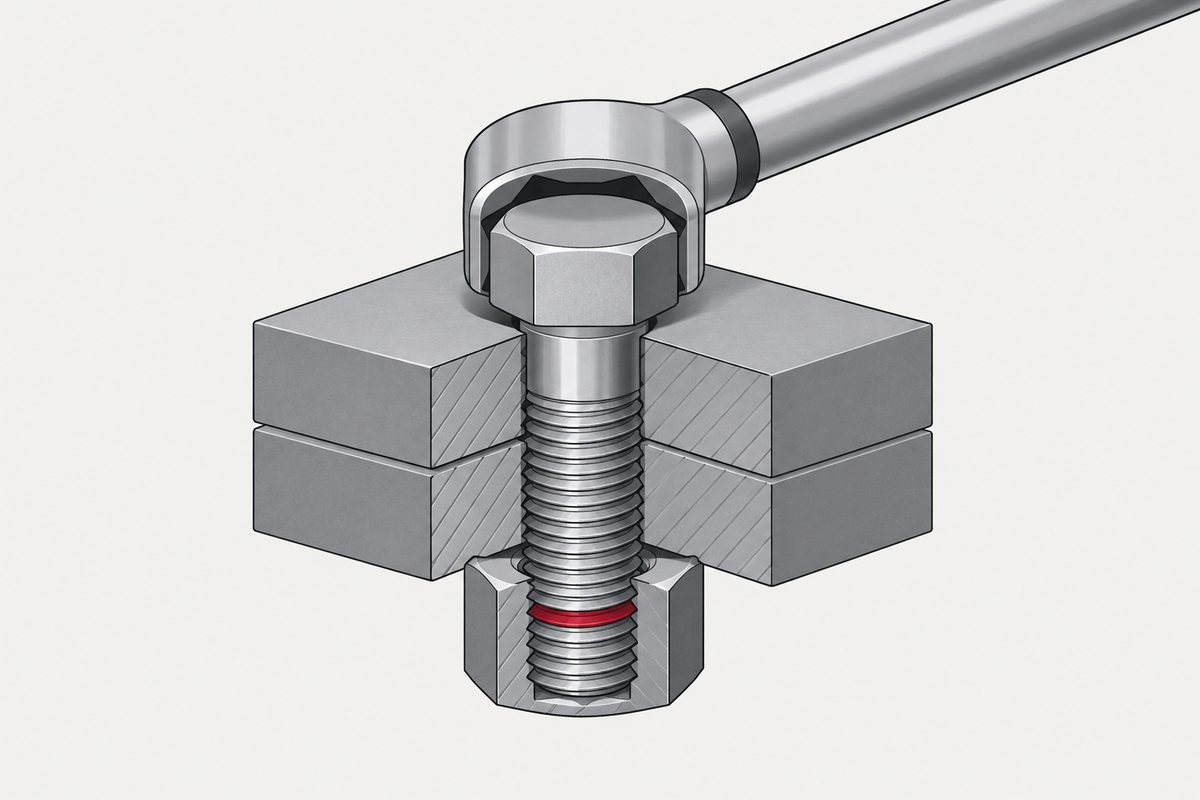
Where the torque actually goes
VDI 2230 Blatt 1 §5.4.3.1 splits the tightening torque into three parts, Equation (127):
MA = FM (0.16P + 0.58 d2 μG + (DKm/2) μK)
The first term raises the load along the thread pitch. The second overcomes thread friction, the third overcomes friction under the head or nut face. Only the first has anything to do with generating preload, and it is the small one.
A worked case from the literature — M8×1.25, d2 = 7.19 mm, mean bearing diameter 11 mm, μG = μK = 0.15 — splits as 12% pitch, 38% thread friction, 50% bearing face. Around 88% of what your wrench reads is being spent on friction.
The familiar “only 10% becomes preload” is a condition, not a constant. It holds for ordinary steel metric joints at μ ≈ 0.14–0.15, and the share moves with pitch, bearing diameter and lubrication. Strictly it is a torque component, not preload — preload is a force. Say about 10 to 15% of the torque goes into raising the load along the pitch and the sentence survives scrutiny.
Friction is the term you cannot see. Your wrench reads the sum and reports it as if it were the first term. VDI's friction class B spans μ = 0.08–0.16 as guidance, though VDI warns that a real batch's spread is not automatically the whole class range.
What the angle converts into, and the term most people drop
Turn the screw through an angle Δφ and the theoretical axial advance relative to the nut is the lead:
Δulead = P ⋅ Δφ / 360°
That advance is not the bolt's stretch. It is shared out: Δulead = ΔlS + ΔlP + Δf — the bolt stretches, the clamped parts compress, and whatever embedding is still happening during the count absorbs the rest. We had this as “stretch times bolt stiffness” in the draft, and the whole chain of reasoning fails with that error in it.
In the elastic range, with the interfaces settled, ΔlS = δSΔFM and ΔlP = δPΔFM, which gives:
ΔFM = (P ⋅ Δφ / 360° − Δf) / (δS + δP)
The denominator is both compliances added together. A soft gasket or a thick coating stack raises δP and swallows angle; a short, stiff, all-steel joint has a small δS + δP and converts the same angle into far more force. Which side of that you are on decides how forgiving the method is.
The compliances themselves come from the same place as everything else in a bolted joint — see the bolt is a spring, and so is the joint.
Snug torque and threshold torque are two different numbers
VDI keeps them apart. Snug torque (Fügemoment) is the preliminary torque that closes the interfaces so the parts are genuinely in contact. Threshold torque (Schwellmoment) is the reference point at which the tool starts counting angle, and it sits above the snug torque.
The reason for the gap is embedding. Anything the interfaces are still doing while the count is running shows up as Δf in the equation above — angle that produced no preload. Starting the count higher pushes most of that behaviour into the part of the tightening that is not being measured.
“Seating torque” gets used loosely for both in the trade. If a drawing calls for one, ask which of the two it means before you set the tool.
What Table A8 actually says about the scatter
The guide values for the tightening factor αA, VDI 2230 Blatt 1 Table A8:
| Method | αA | Scatter |
|---|---|---|
| Yield-point controlled | 1.2–1.4 | ±9% to ±17% |
| Angle controlled | 1.2–1.4 | ±9% to ±17% |
| Hydraulic pulse tool, torque and angle controlled | 1.2–2.0 | ±9% to ±33% |
| Torque control, target torque determined experimentally on the original joint | 1.4–1.6 | ±17% to ±23% |
| Torque control, friction estimated, friction class B | 1.6–2.0 | ±23% to ±33% |
| Torque control, friction estimated, friction class A | 1.7–2.5 | ±26% to ±43% |
| Impact wrench, stalling driver, or by feel | 2.5–4.0 | ±43% to ±60% |
Table A8 does not give 1.0 for angle or yield control. It gives 1.2 to 1.4. The value αA = 1 comes from a separate instruction in the calculation sequence R1, to be substituted for these two methods when sizing the bolt. Those are different statements and we had them merged.
The reason for the R1 rule is worth reading, because the obvious guess is wrong. It is not that the scatter has been accounted for elsewhere in FM min and FM max. VDI §5.4.3.4 gives the mechanism: when friction runs low and the axial preload rises, the torsional stress in the bolt falls at the same time, so the equivalent stress stays bounded by the yield condition. There is no need to size the bolt against a larger possible axial force. VDI states plainly that the real αA is still greater than one; it is simply not used for sizing.
The clearest evidence that the scatter has not gone away is R10/3. For yield and angle control the maximum surface pressure is checked as pmax = 1.4 FMTab / Ap min ≤ pG, and that 1.4 is assembled from the yield-strength scatter itself: 1.2 for the max-to-min yield ratio, divided by 0.9, times 1.05 for work hardening. The scatter was moved, not removed.
Yield-point control is a different thing from a torque-to-yield bolt
Yield-point controlled tightening is a closed-loop method: the tool watches the torque-versus-angle gradient dM/dφ and stops when it starts to fall, which is where the bolt begins to yield. Torque-to-yield describes a bolt that has been tightened to or past its yield point, however that was achieved. They are related, and they are not two names for one thing.
The distinction has a practical edge. For genuine gradient-based yield control, VDI takes the plastic elongation to be small and reusability to be barely affected. TTY bolts driven well into the plastic range in a torque-plus-angle sequence are usually restricted to single use by the manufacturer. Research on reused cylinder head bolts supports the manufacturers' replacement requirement for those particular joints, and that finding does not generalise to every bolt tightened past yield.
Whether a specific bolt can be reused is settled by the OEM service specification, the permitted length, and the plastic elongation and damage criteria — not by ISO 898-1, whose scope excludes torque/clamp-force performance and points to ISO 16047 for it.
Why the industry adopted it at all: over-elastic angle and yield control use more of the bolt's strength and lower the influence of friction scatter on preload. VDI's own M10 12.9 comparison at μG = 0.10–0.14 shows both a tighter spread and a higher achieved preload than torque control. Suitability still depends on bolt ductility, free loaded length, surface pressure and the service strategy.
When torque control is still the right answer
The method with the better table entry is not automatically the method for your joint. Torque control remains the sensible choice when:
- the joint is short and stiff, so the acceptable angle window is too narrow to hold;
- the bolt lacks the ductility or the free deformation length to be taken over-elastic;
- the joint must come apart and go back together without plastic elongation;
- friction, finish and lubrication are controlled, and the target torque has been calibrated on the original joint;
- service or low-volume work has no reliable angle or gradient tool available;
- soft gaskets, thick coating stacks or large unstable embedding would eat the angle.
Table A8's lower αA for torque control is earned under similar conditions — small angles of rotation, a stiff joint, bearing faces that do not gall, and a tool with low output scatter.
One thing does not change with the method: the angle should be determined by test on the original parts, so that the joint's own compliance and interface behaviour are in the number.
Where this connects
The gap between the torque you apply and the clamp force you wanted is in torque and clamp force; how much each method costs you in scatter is in how badly your tightening method controls preload. The compliances in the denominator come from the bolt is a spring, and so is the joint, and temperature moves the result again after assembly — temperature moves preload.
Structural steel runs the same idea with a coarser instrument and a written argument for why it beats torque, in the zero point of the most reliable pretensioning method is the full effort of an ironworker.
References
- VDI 2230 Blatt 1:2015 — §5.4.3.1 and Eq. (127) (torque split); §5.4.3.3 and Fig. 30 (angle control, determination by test); §5.4.3.4 (why αA = 1 is substituted); Table A8 (guide values); R1 and Eq. (130)/(R1/1); R10/3 and Eq. (192) (pmax with the 1.4 factor); Table A5 (friction classes)
- ISO 16047:2005 — torque/clamp-force testing for threaded fasteners; K-factor at §10.1, μtot/μth/μb at §10.2–10.4, yield clamp force and torque at §10.5–10.6
- ISO 898-1 — property classes; scope excludes torque/clamp-force performance and refers to ISO 16047
- Croccolo, De Agostinis and Vincenzi, Engineering Failure Analysis 18 (2011) 364–373 — the M8 torque split, 12/38/50
- NASA fastener training material — the 10/40/50 teaching split; NASA Fastener Integrity Criteria for the “about 90% to friction” statement
- Lee et al., On the Reuse of Bolts Which Have Been Torqued to Yield, 1995 — reused cylinder head bolts
- SAE J174/J174M — torque-tension test procedure; SAE notes the relationship still needs testing on real parts
- VDA 235-203 — practice-oriented tightening behaviour and friction testing, supplementing ISO 16047; not a torque-angle assembly specification
Acceptance for any particular joint is governed by your drawing, your assembly specification and your own calculation.
This is not one of the six steps. It shows up across them, or after assembly. Where the decisions that lead here were made is in specifying a screw, which sets out the order and why doing it out of order is rework.
Common questions
Does turning a fixed angle stretch the bolt by pitch times the angle?
No. Pitch times the angle over 360 gives the theoretical axial advance of the screw relative to the nut. Once the joint is snug that advance is shared between the bolt stretching, the clamped parts compressing, and any embedding still taking place. In the elastic range the preload increment is the advance minus the residual embedding, divided by the sum of the bolt compliance and the clamped-part compliance. Using bolt stiffness alone overstates the preload.
What tightening factor does VDI 2230 give for angle-controlled tightening?
Table A8 gives 1.2 to 1.4, corresponding to a scatter of plus or minus 9 to 17 per cent. The value of 1 that people quote comes from a separate rule in calculation step R1, which instructs you to substitute one for yield-point and angle-controlled tightening when sizing the bolt. That is a design convention, not a claim that the preload has no scatter, and clause 5.4.3.4 says the real tightening factor is still above one.
Why can VDI ignore the tightening factor for yield and angle control?
Because low friction raises the axial preload and lowers the torsional stress in the bolt at the same time, so the equivalent stress stays bounded by the yield condition and the bolt does not need sizing against a larger axial force. The scatter reappears elsewhere: the surface pressure check R10/3 uses 1.4 times the table preload, and that 1.4 is built from the yield strength scatter of 1.2, divided by 0.9, times 1.05 for work hardening.
Is a torque-to-yield bolt the same as yield-controlled tightening?
They are different ideas. Yield-point controlled tightening is a closed-loop method where the tool watches the torque-to-angle gradient and stops when it drops. Torque-to-yield describes a bolt tightened to or past yield by whatever means. VDI treats plastic elongation under genuine gradient control as small, with reusability barely affected, while bolts driven well into the plastic range are usually restricted to single use by the manufacturer.
How much of the tightening torque actually generates preload?
For an ordinary steel metric joint at a friction coefficient near 0.15, roughly 10 to 15 per cent of the torque is spent raising the load along the thread pitch and the rest overcomes thread and bearing-face friction. A published calculation for an M8 by 1.25 screw with a mean bearing diameter of 11 millimetres splits it 12 per cent pitch, 38 per cent thread friction, 50 per cent bearing face. The proportion moves with pitch, bearing diameter and lubrication, so it is not a constant.
Is snug torque the same as threshold torque?
No. Snug torque closes the interfaces so the parts are genuinely in contact. Threshold torque is the reference point at which the tool starts counting angle, and VDI puts it above the snug torque. The gap exists so that embedding finishes before the count begins, since any interface movement during the count is angle that produced no preload.
Enquiries
If a joint is going to be assembled by angle, tell us the grip length, the stack materials and any gasket or coating in the stack when you send the screw. Those set the compliances, and the compliances set how much preload a degree is worth.
Request a quotation
Tell us the part and the quantity. We will come back on feasibility, lead time and price.
Or email us directly sales@tigerfasteners.com