 TIGERFASTENERS
Type 1, 23 and 25 are old names — and type 17 belongs to a different system
Catalogues list type 17, type 23 and type 25 as though they were three standard specifications. Two of those numbers are former designations of letters still in the current standard. The third is not in that standard at all — it is in an Australian one, which defines it by what it must achieve rather than by the point shape every catalogue photographs.
The numbers are the old names of the letters
The current standard is ASME B18.6.3-2024, Machine Screws, Tapping Screws, and Metallic Drive Screws (Inch Series), published 21 June 2024 and superseding the 2013 edition. Tapping screws used to have their own standard, ASME B18.6.4-1998 (R2005), which was merged into B18.6.3 on 5 February 2013.
In the current tables, the designations are letters, with the numbers shown as former designations:
| Current | Former | Where it sits |
|---|---|---|
| D | 1 | Table 4.1.2.2-1, with F, G and T |
| T | 23 | Table 4.1.2.2-1 |
| BT | 25 | Table 4.1.2.1-1, with BF |
So this is not two naming systems running in parallel. It is one system with old names and new. What lost its official standing is the number, not the geometry — D, T and BT are all still in the 2024 body tables.
The letters that never had numbers — AB, B, C, F and the rest — are covered in what the letters actually specify.
Type 17 is in a standard — just not that one
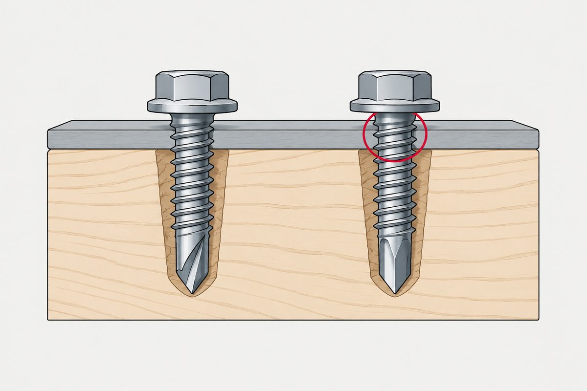
It appears in nearly every timber and roofing catalogue: a sharp auger-style point with a cutting notch or flute cut into the tip, sold for fixing timber, boards and roofing sheet into timber framing. The stated purpose is to lower starting torque, clear chips, and reduce the chance of splitting when fixing near an edge.
It is not in ASME B18.6.3 — not in the current edition’s type lists, not in 2013’s, and no ISO standard defines it. That part matters, because it means type 17 does not belong to the same family as 1, 23 and 25 at all. It has no ASME pilot hole table for the same reason.
It is in AS 3566.1-2002, Self-drilling screws for the building and construction industries, Section 3, “Self-drilling screws for fixing to timber”. Clause 3.1 is headed TYPE, and it reads: self-drilling screws intended for drilling into Type G550 steel to AS 1397 with a maximum thickness of 0.48 mm and hold into timber shall be type 17.
Read the rest of that section, though, and what it pins down is not the shape:
| Clause | What it requires |
|---|---|
| 3.1 Type | Screws that drill 0.48 mm G550 steel and hold into timber shall be type 17 — the type is named by application |
| 3.2 Thread | Preferred thread form and dimensions, ST 3.5 (No. 6) to ST 6.3 (No. 14) — but other thread forms are acceptable provided clauses 3.5 and 3.6 are met |
| 3.5 Torsional strength | Tested to Appendix B, not less than the type ASD values in Table 2.3 |
| 3.6.1 Drill and drive | Hexagon washer head types shall penetrate 0.48 mm G550 steel to AS 1397 |
| 3.6.2 Holding strength | Tested to Appendix E: withdrawal not less than 2.5 kN (ST 4.8), 2.8 kN (ST 5.5), 3.1 kN (ST 6.3) |
So the catalogue and the standard mean different things by the same name. The catalogue means a shape: the notched auger point in the photograph. The standard names that type for an application, then specifies a thread table, a torque floor, a drill-through and a withdrawal force in kilonewtons — and clause 3.2 explicitly allows a different thread form as long as the performance clauses are met.
Which means “type 17” on a drawing can be read two ways, and only one of them can be tested. If the point geometry is what you actually need, that is a drawing requirement or an approved sample, because the standard will accept a screw that meets the numbers with a different thread form.
One narrower claim does survive: the standard sets torque, drill-through and withdrawal thresholds, but no comparative splitting-reduction threshold. So “reduces splitting” remains a manufacturer’s claim rather than a standardised one, and if splitting matters to your application it is still a test to run.
What each type actually specifies
All three share a common description in the standard: a blunt point with tapered entering threads, and one or more cutting edges and chip cavities.
| Type | Thread | Materials the standard lists | Pilot hole table |
|---|---|---|---|
| D (1) | Machine-screw diameter–pitch combinations, approximating Unified form | Aluminium, zinc and lead die castings, sheet and structural steel, cast iron, brass, plastics | Appendix D, Table D-4 |
| T (23) | Same family; flute included angle 90° to 95°, cutting edge above the screw axis | The same broad range | Appendix D, Table D-4 |
| BT (25) | Spaced thread with Type B style tapered entering threads, plus cutting edges and chip cavities | Formally listed for plastics, asbestos and similar compositions | Appendix D, Table D-3 |
Three things we had wrong, and they are the three most commonly repeated:
- T (23) is not “a fine thread for thin metal and plastic”. Its material list is wide, and the standard does not formally define it as a fine-thread type. Its pitch is closer than BT's, which is a comparison, not a category.
- BT (25) is not “the coarse version of 23”. Its actual basis is Type B geometry with cutting edges added. Calling it a coarse 23 is catalogue shorthand.
- Type D does not necessarily have a single longitudinal flute. A single short flute is the historic geometry, described for Type D in BS 4174:1972. The current ASME wording is one or more, so a current product may not match the picture in your head.
One more that catches people: Type F is a thread-cutting type, not a forming type, and it sits in the same table as D, T and G. It is a letter in the same scheme, not another number.
The pilot hole is not one number per type. Appendix D breaks it down by screw size, threads, material thickness or engagement length, and material — steel, aluminium alloy, die-cast zinc and aluminium, cast iron and specific plastics each differ, and the tables state that conditions vary enough that the hole may need changing for the actual application. And type 17 has no ASME pilot hole table at all; whether to pre-drill timber depends on species, density, moisture content, edge distance, screw size and the structural requirement.
Cutting or forming: the actual mechanism
| Thread forming | Thread cutting | |
|---|---|---|
| Mechanism | Displaces material plastically to form the thread | Cutting edges remove material |
| Chips | Generally none | Produces chips |
| What the standard says | For materials that permit greater internal stress (§4.1.1) | Where destructive internal stress is undesirable, or forming drive torque is too high (§4.1.2) |
Research on forming screws defines the process the same way — displacing the parent material to create the thread — and identifies pilot hole diameter as the main parameter governing forming torque and stripping strength.
Four claims about this pairing that need qualifying, all of which we were going to state flatly:
- “Forming types cannot be reinstalled.” Limited reinstallation may be workable, and some plastics design guidance actually prefers forming types for that, because it is easier to find the already-formed thread path again. Genuinely frequent servicing still wants an insert or a nut.
- “Forming resists loosening better because of work hardening.” Overreach. ASME says only that the internal stress from forming can be used to increase resistance in some applications. It does not guarantee superiority under all vibration conditions, and the metal argument does not transfer to plastics.
- “Plastics always take forming types.” Ductile thermoplastics often suit forming. Brittle thermosets, highly filled and high-modulus materials may suit cutting types instead — which is why BT is the type formally listed for plastics.
- “Chips mean it cannot be used in electronics.” Overstated. Electronics generally requires foreign-object-debris risk control rather than a ban on cutting types. Whether it is acceptable depends on whether the chips are enclosed, whether there is chip cavity volume, the assembly sequence, cleaning and inspection, and the risk of short circuit or optical, acoustic or mechanical contamination.
Forming also generally needs higher drive torque than a comparable cutting solution, though specialised low-torque geometries narrow the gap. And the parent material has to tolerate plastic deformation and hoop stress — brittle, very hard or highly filled materials can crack. What the chips actually cost you is in swarf is not a cleanliness problem, and the plastics side is in screws for plastic.
The 2:1 rule is not a standard
The rule of thumb that stripping torque should be at least twice the driving torque circulates widely, usually as though it came from a standard.
We found no general mandatory 2:1 requirement in ASME or ISO. The ratio is traceable to a plastics design handbook, where it is offered as possibly acceptable for skilled operators using hand tools — and the same source suggests around 5:1 for production with power tools.
So quoting 2:1 at a supplier as a requirement is quoting the loosest case in the source, under conditions your production line probably does not match.
Types the standard steers away from
Two types are explicitly discouraged for new design, and they are not the numbered ones:
- Type C was moved to Mandatory Appendix VI, on declining use and generally higher drive torque.
- Type A dimensions are given for reference only, with the more general Type AB recommended instead.
Those are the two worth knowing about, and they are covered in the letters article.
The metric side has no equivalent numbers
ISO has a tapping screw system, and it does not map onto 1, 23 and 25 at all:
- ISO 1478:1999 (second edition, reconfirmed July 2024) specifies the ST tapping screw thread
- ISO 2702:2022 (fourth edition) specifies mechanical and physical properties for heat-treated steel tapping screws, ST2.2 to ST9.5
- ISO 1481, 1482, 1483, 7049 and 7050 specify products by head style
There is no official “ISO type 1 equals…” conversion. The numbered types come from the inch series, and ASME B18.6.3's own title says so. Older British material such as BS 4174 also used D, T and BT with the numbers noted, and Asian catalogues carry them on — but that is inheritance, not an ISO equivalent.
And if you have not yet established that the screw in your hand is an inch screw at all, the prior question is a different one: the pitch will not separate #10-32 from M5, so measuring the pitch cannot decide that pair.
What to ask, and what to put on the drawing
- If the drawing says type 23, ask whether the supplier is working to ASME B18.6.3 Type T. They usually are — but the number alone does not invoke a standard.
- If it says type 17, ask whether you mean the shape or the performance. AS 3566.1 will accept a different thread form that meets its torque, drill-through and withdrawal numbers, so if the point geometry is what you actually need, it belongs on the drawing or in an approved sample.
- Name the material before the type. The same type behaves differently in ductile aluminium and in a filled thermoset, and the standard's own pilot hole tables are organised by material for that reason.
- Do not quote a pilot hole from a type alone. Appendix D needs size, engagement and material together.
- If you cite a strip-to-drive ratio, cite the tool. Hand tools and production power tools are not the same case.
References
- ASME B18.6.3-2024, Machine Screws, Tapping Screws, and Metallic Drive Screws (Inch Series), published 21 June 2024 — Table 4.1.2.1-1 (types BF and BT), Table 4.1.2.2-1 (types D, F, G and T), Nonmandatory Appendix D Tables D-3 and D-4 (approximate hole sizes), Mandatory Appendix VI (Type C)
- ASME B18.6.3-2013 — §4.1.1 (thread forming), §4.1.2 (thread cutting), §4.1.2.1 (BT), §4.1.2.2 (D, F, G, T), §4.1.1.5 (Type C), §§4.1.1.1 and 4.1.1.4 (Type A)
- ASME B18.6.4-1998 (R2005) — merged into B18.6.3 on 5 February 2013
- BS 4174:1972 §3.3(3) — the historic single-flute description of Type D
- ISO 1478:1999 (ST thread, reconfirmed July 2024); ISO 2702:2022 (heat-treated tapping screws, ST2.2–ST9.5); ISO 1481, 1482, 1483, 7049, 7050 by head style
- AS 3566.1-2002 (R2015), Self-drilling screws for the building and construction industries — General requirements and mechanical properties — Section 3 “Self-drilling screws for fixing to timber”: §3.1 TYPE, §3.2 THREAD (Figure 3.1, ST 3.5–ST 6.3), §3.5 torsional strength (Appendix B), §3.6.1 drill and drive capacity, §3.6.2 holding strength (Appendix E, Table 3.3)
- Michael J. Troughton (ed.), Handbook of Plastics Joining: A Practical Guide — the strip-to-drive ratio, approximately 5:1 for power-tool production and 2:1 for trained operators using hand tools
- Stéphan, Mathurin and Guillot, 2012 — pilot hole diameter as the governing parameter for forming torque and stripping strength
Acceptance for any particular application is governed by your drawing and your own testing.
Correction, 26 August 2026. This article first went up saying type 17 was not in any standard. That was wrong: AS 3566.1-2002 §3.1 requires screws in its timber-fixing scope to be type 17, and §§3.2 to 3.6 specify its thread, torsional strength and withdrawal performance. The section above has been rewritten around what that standard actually requires. Our reading had been based on the ASME and ISO catalogues alone, which is exactly the mistake the rest of this article is about — assuming one standards family covers the whole subject.
This page covers step 2, the thread. The whole order is substrate, thread, head, drive, finish, documentation, and why doing it out of order is rework rather than a tweak is in specifying a screw.
Common questions
Are type 1, type 23 and type 25 still in the standard?
The geometries are; the numbers are former designations. The current ASME B18.6.3-2024 tables use letters, with the numbers shown as the old names: D was 1, T was 23 and BT was 25. D, T, F and G appear in Table 4.1.2.2-1 and BF and BT in Table 4.1.2.1-1. So this is one naming system with old and new names rather than two systems in parallel, and what lost official standing is the number rather than the product.
Is type 17 a standard designation?
Yes, but not in the standard the other numbers come from. It is absent from the type lists of ASME B18.6.3 in both the current and the 2013 edition, and no ISO source defines it. It is specified in AS 3566.1-2002, Section 3, where clause 3.1 requires that screws intended to drill 0.48 mm G550 steel and hold into timber shall be type 17. Note that the standard defines the type by application and performance rather than by the notched point shape, and clause 3.2 expressly allows other thread forms that meet the torsional strength and performance clauses.
What is type 25 for?
ASME formally lists Type BT, formerly 25, for plastics, asbestos and similar compositions. Its basis is Type B spaced-thread geometry with cutting edges and chip cavities added, so describing it as a coarse version of type 23 is catalogue shorthand rather than the standard definition. Its approximate hole sizes are in Nonmandatory Appendix D, Table D-3, which is organised by screw size, engagement and material rather than giving one hole per type.
Is thread forming always better than thread cutting?
No, and the standard treats them as different answers to different conditions. Forming displaces material plastically and generally produces no chips, and ASME associates it with materials that permit greater internal stress. Cutting removes material through cutting edges and is used where destructive internal stress is undesirable or where forming would need too much drive torque. Forming also generally requires higher drive torque, and the parent material has to tolerate plastic deformation and hoop stress.
Should stripping torque be at least twice the driving torque?
That ratio is a rule of thumb rather than a standard requirement; we found no general mandatory 2 to 1 rule in ASME or ISO. It traces to a plastics design handbook where it is offered as possibly acceptable for skilled operators using hand tools, and the same source suggests around 5 to 1 for production using power tools. So the figure needs the tooling stated alongside it, or it is being quoted at its loosest case.
Do thread-forming screws prevent reuse?
Not necessarily. Limited reinstallation may be workable, and some plastics design guidance actually prefers forming types for that purpose because the already-formed thread path is easier to find again. Where servicing is genuinely frequent, the durable answer is a metal insert or a nut rather than relying on a thread created during the first installation.
Enquiries
If a drawing calls for a numbered type, tell us the parent material as well. The same type behaves differently in ductile aluminium and in a filled thermoset, and the standard's own hole tables are organised by material for exactly that reason.
Request a quotation
Tell us the part and the quantity. We will come back on feasibility, lead time and price.
Or email us directly sales@tigerfasteners.com