 TIGERFASTENERS
A Loose Bolt Does Not Make a Weak Joint, It Makes a Different One
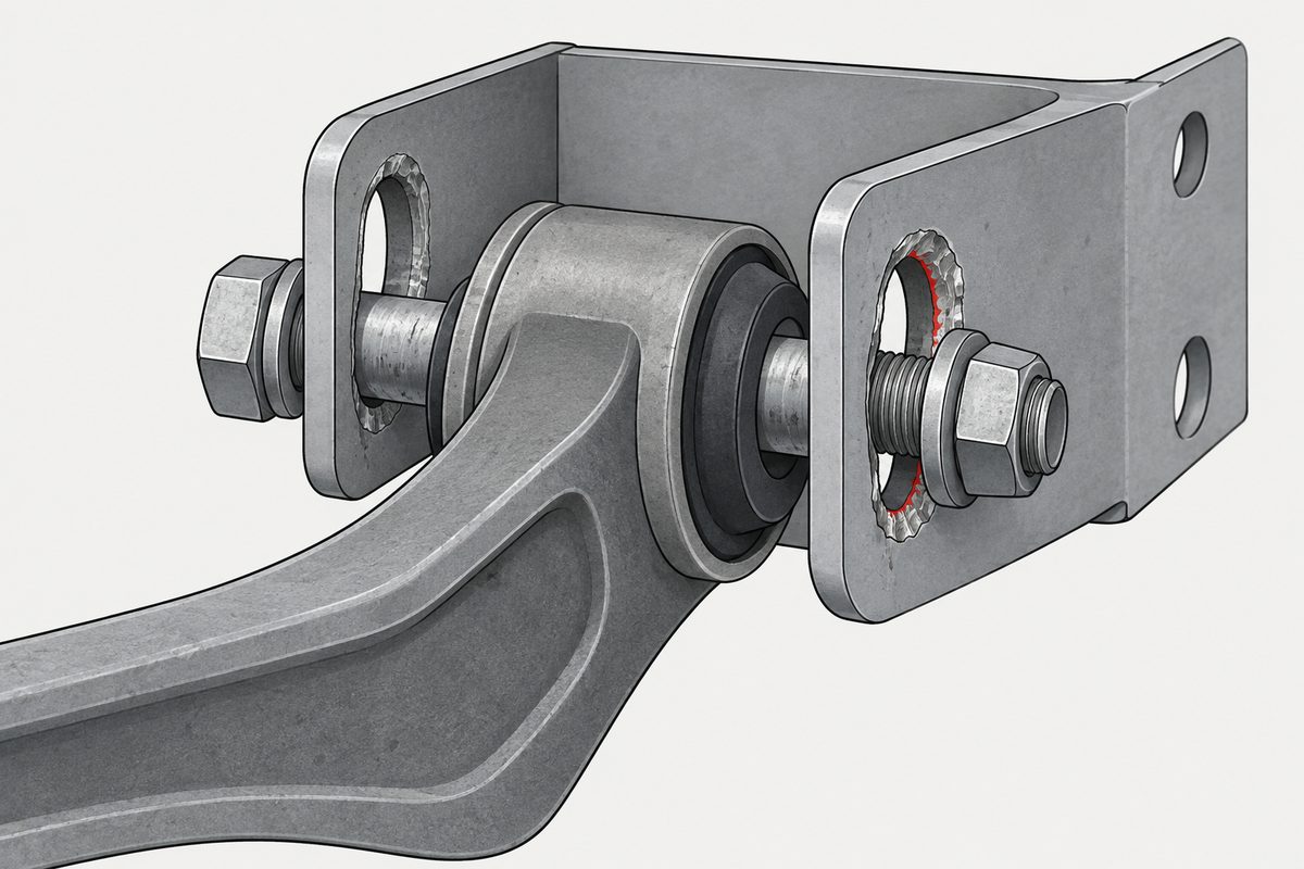
A shop posted a photograph of a chassis after another shop had replaced two control arms and left the bolts untightened. The bolts had eaten through the frame, and the vehicle was driven that way until it was towed in. Nine hundred and forty seven upvotes. The reason a loose bolt destroys a hole rather than simply carrying less load is written out formally in a free specification, in an equation where the pretension is one of the multipliers.
The slip resistance of a bolted joint is Rn = µ · Du · hf · Tm · ns · ksc, where Tm is the bolt pretension. The pretension is a multiplier. Take it to zero and the product is zero. The friction path does not get weaker, it stops existing, and the joint reverts to the other kind: bolts in bearing against the sides of their holes.
The document is a structural steel specification for buildings and bridges. It is the RCSC Specification for Structural Joints Using High-Strength Bolts, dated 11 June 2020, one hundred and eighteen pages, free to download in full. It has nothing to say about vehicles, and we are not applying its numbers to one. We are quoting it because it does something almost no other free document does: it defines the two kinds of shear joint side by side, in one glossary, so you can read them against each other.
We also do not diagnose the chassis in the photograph, which we have not seen in person, and we name no vehicle.
Two definitions, one glossary
Here they are, in the specification’s own words.
Shear/Bearing Joint. A snug-tightened joint or pretensioned joint with bolts that transmit shear loads and for which the design criteria are based upon the shear strength of the bolts and the bearing strength of the connected materials.
Slip-Critical Joint. A joint that transmits shear loads or shear loads in combination with tensile loads in which the bolting assemblies have been installed to provide a pretension in the installed bolt (clamping force on the faying surfaces), and with faying surfaces that have been prepared to provide a calculable resistance against slip.
Same bolts, same holes, same plates. What differs is where the load goes. In one, the load crosses the joint as friction between two clamped surfaces and the bolt never feels it as shear. In the other, the plates slide until metal meets metal and the bolt shank carries the load across the gap while the hole wall carries it into the plate.
The quantity that decides which one you have is defined too. The mean slip coefficient is “the ratio of the frictional shear load at the faying surface to the total normal force when slip occurs”. Friction load over normal force. No normal force, no friction load.
The equation says it more bluntly than any sentence could
Section 5.4 gives the nominal slip resistance per bolt. Reading the terms is the whole argument.
- µ, the mean slip coefficient, from the surface condition
- Du, 1,13 for building structures and 1,00 for bridge structures
- hf, a filler factor, 1,0 or 0,85
- Tm, the minimum bolt pretension
- ns, the number of slip planes
- ksc, a reduction when the same bolts also carry applied tension
Every one of those is multiplied together. That is our reading of the arithmetic rather than a sentence in the standard, but the arithmetic is not ambiguous: slip resistance is directly proportional to pretension. Halve the pretension and you halve the resistance to slip. Take it to zero and there is nothing left to reduce.
This is why a joint left untightened does not behave like a slightly worse version of a tight one. It has changed category. The design criteria that now apply are the ones in the other definition, and nobody chose them.
How far it moves before the bolt touches the hole
The commentary to section 4.1 answers the question that the photograph raises, and it answers it with a number.
“The maximum amount of slip that can occur in a joint is, theoretically, equal to twice the hole clearance. In practical terms, it is observed in laboratory and field experience to be much less; usually, about one-half the hole clearance.”
So how much clearance is there? Table 3.1 gives the nominal hole dimensions, and the clearances below are our subtraction from it.
| Bolt | Standard hole | Clearance | Oversized hole | Clearance |
|---|---|---|---|---|
| 1/2 in | 9/16 | 1/16 | 5/8 | 1/8 |
| 5/8 in | 11/16 | 1/16 | 13/16 | 3/16 |
| 3/4 in | 13/16 | 1/16 | 15/16 | 3/16 |
| 7/8 in | 15/16 | 1/16 | 1 1/16 | 3/16 |
| 1 in | 1 1/8 | 1/8 | 1 1/4 | 1/4 |
| 1 1/8 in and up | d + 1/8 | 1/8 | d + 5/16 | 5/16 |
The standard clearance is 1/16 in from half an inch up to seven eighths, and then it doubles to 1/8 in at one inch and stays there. That doubling in a single step of the table is ours to point out; the standard just prints the hole diameters.
Now put the two together for a three quarter inch bolt in a standard hole. Clearance 1/16 in. Theoretical maximum slip, twice that, is 1/8 in, about 3,2 mm. Observed slip, about half the clearance, is 1/32 in, roughly 0,8 mm. Put the same bolt in an oversized hole and the clearance triples, so the theoretical maximum slip becomes 3/8 in, about 9,5 mm.
A few millimetres. That is the entire distance between a joint that is holding and a joint where the shank is against the hole wall. And the commentary adds that this often happens before any load is applied at all: “Acceptable inaccuracies in the location of holes within a pattern of bolts usually cause one or more bolts to be in bearing in the initial, unloaded condition.”
The surface does more work than the bolt grade
The other term worth staring at is µ, because it is not a property of the fastener at all. The specification gives two values.
- Class A, µ = 0,30. Unpainted clean mill scale steel surfaces, or surfaces with Class A coatings on blast-cleaned steel, or hot-dipped galvanized
- Class B, µ = 0,50. Unpainted blast-cleaned steel surfaces, or surfaces with Class B coatings on blast-cleaned steel
Class B is five thirds of Class A, which is our division, so blast cleaning the faying surfaces buys about two thirds more slip resistance than leaving mill scale on them. Nothing about the bolt changed. And note where galvanizing lands: hot dip galvanized is named inside the Class A group, not Class B.
This is the second time in a week that a faying surface has turned out to be the thing that matters rather than the hardware bolted through it. The other was a bonding standard that bans star washers because the current crosses at the prepared surfaces and the fastener is only there to hold pressure on them. Same geometry, two different jobs, and in both cases the fastener supplies clamping force rather than doing the work itself.
Where the specification stops allowing snug tight
Snug tightened joints are permitted by default. Section 4.2 then lists where pretension becomes mandatory, and section 4.3 where the joint must be slip critical. Two entries are worth reading with a moving structure in mind, whatever the structure is.
- Pretensioned joints are required for joints subject to significant load reversal, and for joints subject to fatigue load with no reversal of the loading direction
- Slip-critical joints are required for joints subject to fatigue load with reversal of the loading direction, for joints using oversized holes, for most slotted holes, and where slip at the faying surfaces would be detrimental to the performance of the structure
The commentary explains the first of those in one sentence: joints subject to reversed fatigue load “must be slip-critical joints since slip may result in back and forth movement of the joint and have potential for accelerated fatigue failure”. Back and forth movement. Not one slip and then bearing, but a joint that arrives at the hole wall, comes back, and arrives again.
That is the mechanism in the photograph, and it is why the damage was to the hole rather than to the bolt. This site has looked at what snug tight actually means in that specification, which is a different question from this one and is not repeated here.
A hole that grew is a different hole
Two more provisions close the loop. The hole type is not just a description, it carries a price: the resistance factors differ by hole type.
| Hole type | φ (LRFD) | Ω (ASD) |
|---|---|---|
| Standard, and short slots perpendicular to the load | 1,00 | 1,50 |
| Oversized, and short slots parallel to the load | 0,85 | 1,76 |
| Long slotted | 0,70 | 2,14 |
Two observations, both ours. First, a long slot costs thirty percent of the slip resistance relative to a standard hole. Second, and more satisfying, the allowable stress factors are just 1,50 divided by the load factors: 1,50 ÷ 0,85 = 1,7647, printed as 1,76, and 1,50 ÷ 0,70 = 2,1429, printed as 2,14. Two rows, two exact matches. The standard never states the relationship.
And the commentary to Table 3.1 makes the consequence explicit for a hole that is not the size it was meant to be: “When the dimensions of bolt holes are such that they exceed these permitted variations, the bolt hole must be treated as the next larger type.” A hole that has grown is not a standard hole with a note against it. It is an oversized hole, with the reduction that comes with that, and if it keeps growing it is a slot.
What to take from it
- Slip resistance is proportional to pretension. The pretension is a multiplier in the slip equation, so zero pretension gives zero slip resistance rather than reduced resistance
- A joint without pretension is a different design case, governed by the shear strength of the bolts and the bearing strength of the connected material
- The distance to the hole wall is small. Theoretical maximum slip is twice the hole clearance and observed slip is about half of it, so a three quarter inch bolt in a standard hole has roughly 3,2 mm of travel in theory and under a millimetre in practice
- Standard hole clearance is 1/16 in up to 7/8 in bolts, then doubles to 1/8 in at one inch
- The faying surface carries the friction, not the bolt. Blast cleaned is 0,50 and mill scale is 0,30, and hot dip galvanized counts as the lower class
- Reversing fatigue load is where the specification stops allowing a snug tightened joint, because slip becomes back and forth movement
- A hole that has grown past its tolerance is reclassified as the next larger type, and each step up costs slip resistance
- None of these numbers belongs to a vehicle. This is a structural steel specification and it is quoted for the reasoning, not the figures
The bolts in that photograph were never carrying the load the way anyone intended. They were pins in slightly oversized holes, and the frame was the softer of the two things in contact.
Those two categories were not always there. The specification arrived in 1951 as a rule for putting one bolt where a rivet had been, with every joint pretensioned onto bare steel, and the split into kinds came three years later.
Occasionally a joint is meant to move, and then the specification changes shape entirely: one federal rule requires bolts to be tightened so that the parts can still slide, and never mentions torque at all.
This is not one of the six steps. It shows up across them, or after assembly. Where the decisions that lead here were made is in specifying a screw, which sets out the order and why doing it out of order is rework.
Common questions
Why does an untightened bolt damage the hole rather than just carry less load?
Because the joint changes category. Slip resistance in the RCSC specification is the product of the slip coefficient, the pretension and several other factors, so with no pretension there is no slip resistance at all. The plates then slide until the bolt shank meets the hole wall, and the load path becomes bolt shear and bearing on the connected material.
How far can a bolted joint slip?
The commentary to section 4.1 says the maximum is theoretically twice the hole clearance, and that laboratory and field experience puts it at about half the hole clearance in practice. For a three quarter inch bolt in a standard hole the clearance is 1/16 in, so that is about 3,2 mm in theory and under a millimetre observed.
What is the clearance in a standard bolt hole?
By our subtraction from Table 3.1, 1/16 in for bolts from 1/2 to 7/8 in, and 1/8 in from 1 in upwards. Oversized holes give 1/8 in at 1/2 in, 3/16 in from 5/8 to 7/8 in, 1/4 in at 1 in, and 5/16 in above that.
What is a slip-critical joint?
The specification defines it as a joint that transmits shear, or shear with tension, in which the bolts have been installed to provide a pretension, described as clamping force on the faying surfaces, and with faying surfaces prepared to give a calculable resistance against slip. The contrast is a shear/bearing joint, designed on the shear strength of the bolts and the bearing strength of the connected materials.
Does the surface finish change how much a joint can carry?
For slip resistance, yes, and by a lot. The mean slip coefficient is 0,30 for Class A surfaces, which includes unpainted clean mill scale and hot dip galvanized, and 0,50 for Class B, which is unpainted blast-cleaned steel or Class B coatings on it. Class B is five thirds of Class A by our division, with no change to the bolt.
When does the specification require pretension rather than snug tight?
Section 4.2 requires pretensioned joints where the governing code demands it, for significant load reversal, for fatigue load with no reversal, for Group 120 assemblies under tensile fatigue, and for Group 144 or 150 assemblies under tension or combined shear and tension.
Why must a joint under reversing fatigue load be slip-critical?
The commentary says such joints must be slip-critical because slip may result in back and forth movement of the joint, with potential for accelerated fatigue failure. A single slip puts the bolt against the hole; a reversing load takes it back and returns it.
What happens if a bolt hole is bigger than the table allows?
The commentary to Table 3.1 says the hole must be treated as the next larger type. That is not a paperwork change: the resistance factor for slip drops from 1,00 for a standard hole to 0,85 for an oversized one and 0,70 for a long slot.
Does any of this apply to a car or a machine?
Not directly, and this page does not claim it does. The RCSC specification covers structural joints in buildings and bridges. It is quoted here because it states the difference between a friction joint and a bearing joint more plainly than most documents, and because it is free to read in full.
References
- RCSC, Specification for Structural Joints Using High-Strength Bolts, 11 June 2020. Complete, 118 pages, free. Glossary, Table 3.1, sections 4.1 to 4.3 and section 5.4
- r/Justrolledintotheshop, where a photograph of untightened control arm bolts and the damage they did produced the question
The RCSC specification was read in full; it is a free download of 118 pages. It is a structural steel specification for buildings and bridges. It does not apply to vehicles, machinery or anything else, and no figure on this page should be transferred to one. It is quoted for the way it separates the two kinds of shear joint, not for its numbers. We do not diagnose the chassis in the forum photograph, which we have not seen, and no vehicle make or model is named. The following are our own arithmetic or reading, not statements by the specification: that slip resistance is directly proportional to pretension and therefore zero without it, which follows from pretension appearing as a multiplier in Equation 5.6; the ratio of five thirds between the Class B and Class A slip coefficients; the hole clearances obtained by subtracting the bolt diameter from the nominal hole diameter in Table 3.1, and the observation that the standard clearance doubles from 1/16 to 1/8 in at one inch; the worked slip distances for a three quarter inch bolt; and the finding that the allowable stress factors are 1,50 divided by the corresponding load factors, exact in both rows. Equation 5.6 with its slip coefficients, and Table 3.1, were checked against rendered images of the printed pages rather than extracted text. The minimum pretension values in Table 5.2 are not reproduced here, both because this page does not need them and because they are the figures most likely to be taken out of context. We also do not offer the common relation between pretension and tensile stress area, because checking it would require thread pitches and an area formula that this document does not contain. AISC 360, EN 1090 and ASTM F3125 have not been read. We read the forum post and not its replies. What snug tight means in this specification, and the turn of nut method, are covered on an earlier page and are not repeated here.
Enquiries
If a joint on your drawing has to resist shear without moving, say so, because that is a different requirement from a bolt that is strong enough. It changes the surface preparation, the hole type and the tightening method, and none of those is decided by the property class on the bolt.
Request a quotation
Tell us the part and the quantity. We will come back on feasibility, lead time and price.
Or email us directly sales@tigerfasteners.com