 TIGERFASTENERS
The General Tolerance Does Not Reach a Thread Drawn the Normal Way
A machinist posted a print from a European supplier and asked whether the world had moved without telling him. The distances no longer carried plus and minus. Seventeen tapped holes had grown a positional tolerance and a pile of new datums. He wanted to know whether this was really a new standard or whether he was the only one out of the loop. It is a real standard, it has a number, and once you read it the tapped holes stop being a mystery.
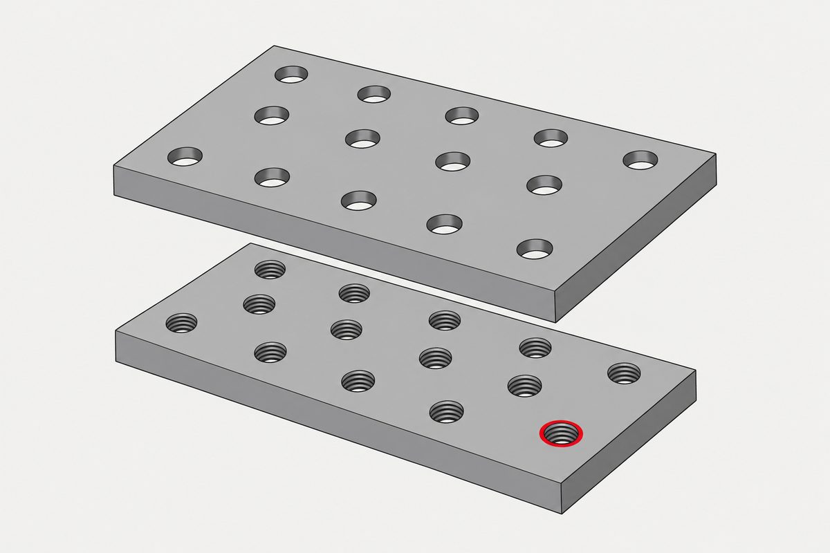
ISO 2768-2:1989 is withdrawn. Its replacement is ISO 22081:2021, and the replacement works differently in two ways that matter on a fastener drawing. It applies only to integral features, which is to say surfaces, and not to derived features. And its Rule D lists four exceptions, the last of which is “an integral feature indicated with simplified representation and not included in the CAD model, for example edges, fillets or screw threads.”
We can now say that plainly, which we could not the last time this site wrote about the title block. An earlier page here said the withdrawal was widely reported but that we had not confirmed it from the source. We have now, twice over. ISO’s own catalogue entry for ISO 2768-2:1989 gives its status as Withdrawn, its stage as 95.99, and names ISO 22081:2021 as the document that revised it. And the foreword of ISO 22081 itself says “this first edition cancels and replaces ISO 2768-2:1989, which has been technically revised.” That earlier page has been corrected.
Only half of ISO 2768 went
This is the part that makes the change confusing to read about. ISO 2768 had two parts and only the second one was withdrawn.
- Part 1, tolerances for linear and angular dimensions, four classes, three pages. Status Published, last reviewed and confirmed in 2022, stage 90.92, to be revised. ISO’s entry adds that it is “expected to be replaced by ISO 2768 within the coming months”, a project that is under development. That is all we know about it and all we will say.
- Part 2, geometrical tolerances, three classes, eight pages. Status Withdrawn, revised by ISO 22081:2021.
So the familiar string ISO 2768-mK now has one live half and one dead half. The m is still pointing at a published document. The K is pointing at a withdrawn one. On a part already in production this changes nothing, because the drawing states which document governs and that statement does not expire. On a drawing you are about to release it is worth knowing which letter is which.
One more difference sits in the two abstracts. Part 2 says it “mainly applies to features which are produced by removal of material”, and Part 1 applies to workpieces “produced by metal removal or formed from sheet metal”. ISO 22081 carries no such restriction in its scope. It is a rule about how to write a general specification, not a table of values for milled parts.
What replaced the three letters
Rule C: the general geometrical specification shall be indicated with a surface profile specification. One characteristic, and the standard says so twice. The sentence under Table 1 repeats it in brackets: the characteristic “can only be surface profile”, though any specification element from ISO 5459 and ISO 1101 may be used alongside it as long as it does not contradict the rules given here.
The only example in Table 1 is a frame reading surface profile, 0,12, A, B, C. And Figure 1 shows the whole thing in a title block:
General tolerances ISO 22081
surface profile | 0,5 | A | B | C
Linear sizes: ±0,25 with the envelope requirement modifier
Angular sizes : ±0,5°
Set that beside ISO 2768-mK and the shape of the change is visible without reading a word of theory. The old callout is one string of two letters and names no datum at all. The new one is four lines, it carries actual numbers, and it demands a three plane datum system. Under the old scheme the letters selected a row in somebody else’s table. Under the new one you write the value.
That last point deserves its own sentence, because it is the one people trip on. ISO 22081 contains no tolerance values. Table 1 is a table of how to indicate, not a table of how much. The standard says the values “can be defined as single values or variable values”, that variable values may depend on the dimensions of the feature or on the distance of the feature to the datum system, and that when they vary you should define unambiguous rules for obtaining them from a table in the drawing set or from another document. Figure 2 is an example that just says “see table 1 in document 123456”. The old standard handed you three classes. This one hands you a blank and a set of rules for filling it in.
Rule D, and the exception with threads in it
Rule D says the general geometrical specification applies to each integral feature independently, with four exceptions. Read as a list they look alike. Read for what they do, they split in two.
- an integral feature specified by a size specification, individual or general
- an integral feature or its derived feature specified by an individual geometrical specification
- a datum feature used in the datum system defined in the datum section of the general geometrical specification
- an integral feature indicated with simplified representation and not included in the CAD model, for example edges, fillets or screw threads
The first two are precedence, not exclusion. They say that where you have already specified a feature individually, your individual specification wins. Nothing falls through the floor. The third and fourth are the ones that genuinely put a feature outside the general tolerance, and the fourth is the one with fasteners in it.
Note the condition carefully, because it is two conditions joined by an and. The feature has to be indicated with simplified representation and not included in the CAD model. A thread drawn the way threads are normally drawn, as a circle and a broken circle or as two lines beside the shank, with no helix in the model, meets both. So on the overwhelming majority of real drawings, the general geometrical specification does not reach the thread at all. If you want anything controlled on that thread, you specify it.
Which is a rule the fastener world already lives by from the other direction. The thread has its own tolerance system, in classes such as 6g and 6H, and that system does not interact with a general profile tolerance on the surfaces around it (what a thread class actually controls). ISO 22081 makes the separation explicit rather than leaving it to be inferred.
Why seventeen tapped holes grew their own callout
Back to the print that started this. The scope of ISO 22081 is narrow in a way that is easy to skim past:
“The general geometrical specifications and general size specifications defined in this document apply only to integral features (including features of size). These specifications do not apply to derived features or integral lines.”
An integral feature is defined in clause 3.3 as a geometrical feature belonging to the real surface of the workpiece or to a surface model. A surface. Something you could touch with a probe.
The axis of a hole is not a surface. That inference is ours, not a sentence in the standard, and the standard points at ISO 17450-1 for the formal definitions, which we have not read. But if the general geometrical specification reaches only surfaces, then the position of a hole axis is not something it can control, and a designer who wants the location of a tapped hole held has no option but to write an individual positional tolerance with datums attached. Which is precisely what appeared on that print, seventeen times.
So the two things that looked like a European affectation are the same thing. The distances lost their plus and minus because location is not a size, and the taps grew positional callouts and datums because location has to be specified individually or it is not specified at all. The pile of new datums is not padding. It is the datum system the general specification is required to reference, doing the work the old H, K and L classes used to do without one.
There is a second standard that arrives at the same place from the measurement side. It says that a distance between two derived features, which is what a hole pattern is made of, is not a size at all, and that a plus and minus tolerance on it is ambiguous on a real part. Same conclusion, different route: the location of an axis is not something an ordinary dimension can pin down.
We are not judging the drawing itself. We do not have it, and a rule can be correctly invoked and still applied badly. What we can say is that the framework the supplier is working in is real, current, and published.
The two warnings the standard gives its own users
Clause 4.1 opens by telling designers what general specifications cost them. The risks it names are “overlooking important functional requirements” and “selecting unnecessarily tight tolerances regarding the functional requirement”. It then puts the burden back where it belongs: it is the designer’s responsibility to ensure that “the entire part, i.e. all geometrical features, is completely and unambiguously specified.”
That is the same argument this site made about the old title block string from the purchasing side, and it is good to find it in the standard’s own words. A general tolerance is a statement about everything you did not think worth toleranding individually, and it will be held against the whole part.
One more line worth carrying away. Note 2 under Rule D says the general geometrical specifications are in accordance with the independency principle and the feature principle. Independency means a size deviation and a form deviation are checked separately unless something says otherwise, which is why the example in Figure 1 puts the envelope requirement modifier back on the linear sizes by hand. If you want size and form coupled on this drawing, you ask for it.
What to take from it
- ISO 2768-2:1989 is withdrawn, stage 95.99, revised by ISO 22081:2021. Confirmed from ISO’s catalogue and from the replacement’s own foreword
- ISO 2768-1:1989 is still published, confirmed in 2022, stage 90.92 to be revised, with a replacement in development. So half of an ISO 2768-mK callout is live and half is not
- The new general geometrical specification is a surface profile tolerance to a datum system. One characteristic only, and a datum system is part of the callout
- There are no classes and no tolerance values in ISO 22081. You supply the number, on the drawing or in a referenced document
- It applies to integral features only. Surfaces, and features of size. Not derived features, not integral lines
- Rule D excepts threads that are indicated with simplified representation and not included in the CAD model, which describes almost every thread on almost every drawing
- A tapped hole pattern therefore needs its own positional tolerance and datums. The general tolerance cannot locate an axis
The machinist in that thread asked whether he was the only one out of the loop. He was not, and the loop has a document number. The awkward part is that the change is thirty one years in the making and lives in a fourteen page standard that says almost nothing about how tight anything should be.
This page covers step 6, the documentation. The whole order is substrate, thread, head, drive, finish, documentation, and why doing it out of order is rework rather than a tweak is in specifying a screw.
Common questions
Is ISO 2768-2 still valid?
No. ISO gives its status as Withdrawn, at stage 95.99, and names ISO 22081:2021 as the document that revised it. ISO 22081 says the same thing from the other side: its foreword states that the first edition cancels and replaces ISO 2768-2:1989. A drawing already released against ISO 2768-2 still means what it said, because the drawing names the governing document.
Is ISO 2768-1 also withdrawn?
No. It is published, was last reviewed and confirmed in 2022, and sits at stage 90.92, to be revised. ISO’s entry says it is expected to be replaced by a standard numbered ISO 2768 within the coming months, and that project is under development. We have not read the draft and say nothing about it.
What replaced the H, K and L classes?
A surface profile tolerance referenced to a datum system, written out in or near the title block. Rule C of ISO 22081 states that the general geometrical specification shall be indicated with a surface profile specification, and the note under Table 1 adds that the characteristic can only be surface profile.
Does ISO 22081 tell me what tolerance to use?
It does not. The standard gives rules for indicating and interpreting a general specification, not values. Tolerance values can be single or variable, variable ones may depend on the size of the feature or its distance from the datum system, and where they vary the standard expects unambiguous rules for obtaining them from a table in the drawing set or from another referenced document.
Does the general tolerance apply to screw threads?
Not to a thread indicated with simplified representation and not included in the CAD model, which is the fourth exception in Rule D and describes how threads are drawn on most drawings. Both conditions have to be met. Anything you need controlled on the thread has to be specified individually.
Why does a drawing to ISO 22081 have so many datums?
Because the general geometrical specification is a profile tolerance and a profile tolerance references a datum system. The example in Figure 1 shows three datum letters. Under ISO 2768-2 the general geometrical classes needed no datum at all, so a drawing moving to the new document acquires a datum system it did not previously have to declare.
Can a general tolerance control the position of a tapped hole?
Our reading is that it cannot. ISO 22081 applies only to integral features and explicitly not to derived features, and clause 3.3 defines an integral feature as one belonging to the real surface of the workpiece. An axis is not a surface. The standard does not spell this consequence out and refers to ISO 17450-1 for the formal definitions, which we have not read, so treat the conclusion as ours.
What is the independency principle doing here?
Note 2 under Rule D states that the general geometrical specifications are in accordance with the independency principle and the feature principle. In the worked example in Figure 1 the linear sizes carry the envelope requirement modifier explicitly, which is what you would expect if the default is independence and the designer wants size and form coupled on those features.
Which standard defines the modifiers like CZ and UZ?
Not this one. ISO 22081 says that apart from the characteristic, specification elements from ISO 5459 and ISO 1101 may be used. We have not read either, and this page does not explain any modifier from them.
References
- ISO 22081:2021, Geometrical product specifications (GPS), geometrical tolerancing, general geometrical specifications and general size specifications. Foreword, introduction, clauses 1 to 5.2, Table 1, Figures 1 and 2
- ISO 2768-2:1989, the withdrawn geometrical part, catalogue entry giving status, stage and revision
- ISO 2768-1:1989, the published dimensional part, catalogue entry giving status, review date and stage
- r/Metrology, where a print full of positional callouts and datums produced the question
ISO 22081:2021 was read from the publicly available iTeh preview, which reaches printed page 4 and covers the contents list, foreword, introduction, scope, normative references, terms, clause 4 in full, and clauses 5.1 and 5.2. Clause 5.3 on datum systems, clause 6 on general size specifications, Table 2 and all three annexes are outside the preview, and nothing from them is quoted or characterised here. The catalogue facts for all three standards were read from ISO’s own pages in a browser: ISO 22081:2021 is a first edition, February 2021, fourteen pages, ISO/TC 213, ICS 17.040.40, stage 90.93, confirmed in 2026; ISO 2768-2:1989 is withdrawn at stage 95.99, eight pages, revised by ISO 22081:2021; ISO 2768-1:1989 is published at stage 90.92, three pages, confirmed in 2022, with a replacement under development. The following are our own arithmetic or reading rather than statements by any of these documents: the observation that the first two exceptions in Rule D are precedence rather than exclusion, the comparison of a two letter ISO 2768 callout with the four line indication in Figure 1, the page count comparison, and above all the conclusion that the general geometrical specification cannot control the position of a hole axis, which follows from the scope excluding derived features and clause 3.3 defining an integral feature as belonging to the real surface, but which the standard does not state in those words. ISO 17450-1, where the formal definitions of integral and derived features live, has not been read. The tolerance classes and values of ISO 2768-2 are not reproduced here; that document was not read, and its description comes from ISO’s published abstract. The modifiers asked about in the forum thread belong to ISO 1101 and ISO 5458, neither of which we have read, and neither is explained on this page. We do not evaluate the drawing in the thread, which we have not seen, and we name no company. We read the post and not its replies. Figure 1, Figure 2, Table 1 and the wording of Rule D were checked against rendered images of the printed pages rather than extracted text. This page corrects an earlier one: the ISO 2768 title block page previously said the withdrawal of Part 2 was widely reported but unconfirmed, and that wording has been replaced.
Enquiries
If your drawing carries a general tolerance, tell us which document it points at and, for ISO 22081, what value goes in the profile frame and which features are the datums. If it still says ISO 2768 with two letters, that is fine and we will read it, but say so, because the two halves of that string now have different statuses.
Request a quotation
Tell us the part and the quantity. We will come back on feasibility, lead time and price.
Or email us directly sales@tigerfasteners.com