 TIGERFASTENERS
You Cannot Put a Caliper on an Axis, and That Is the Smaller Problem
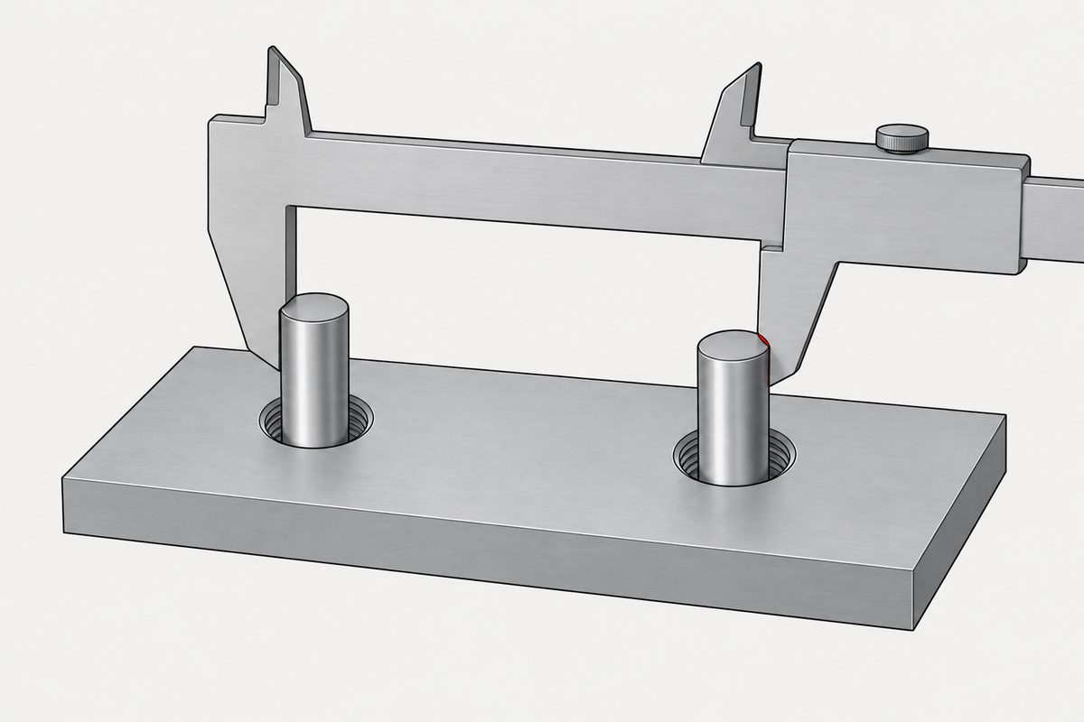
Someone designing a bracket asked how to physically measure the centre distance between two tapped M3 holes without introducing alignment error. A hundred and thirty three upvotes and a hundred and thirty seven replies, most of them about technique. There is a standard whose entire purpose is the layer underneath that question, and it says something uncomfortable: for a dimension of this kind, a plus and minus tolerance is ambiguous on a real part, and it does not recommend using one.
ISO 14405-2:2018, clause 4: “For dimensions other than linear or angular sizes, a requirement with ± tolerancing is ambiguous (specification ambiguity) when applied to a real workpiece. This type of specification is not recommended.” A centre distance between two hole axes is such a dimension. Before there is a question about how to measure it, there is a question about what the number means.
This page does not give measuring technique. We do not have that part, we have no measurements of our own, and the thread already contains a hundred and thirty seven opinions about fixtures. What we can add is the layer the standard occupies: what kind of dimension a centre distance is, and why the document that owns it spends its whole length arguing that the usual way of writing it down is the wrong one.
A size and a distance are different things
The standard separates two words that everyday usage runs together. Clause 3.2 defines linear size as a “dimension in length units characterizing a feature of size”. Clause 3.4 defines distance as a “dimension between two geometrical features which are not considered as a feature of size”.
The note that follows matters for the question: “Distance can be between two integral features or an integral feature and a derived feature or two derived features.” Three cases, and the third one is the case in the forum post.
An integral feature is a surface, something a probe can touch. A derived feature is not. This site established that reading from a different document when it looked at why a general tolerance cannot control the position of a hole, and it is worth repeating that the reading is ours: neither standard says in so many words that the axis of a hole is a derived feature. What ISO 14405-2 does say is that a distance can run between two derived features, and that such a distance is not a size.
So the caliper is measuring the wrong category of thing before it is measuring it badly. It is an instrument for two-point sizes, and there is no pair of points on the part whose separation is the centre distance.
Why the standard calls it ambiguous
The introduction gives the reason in one sentence, and it is not about instruments at all.
“For dimensions other than linear or angular sizes, the requirement is ambiguous when applied to the real workpiece. It is the presence of form and angular deviations on all real workpieces that makes these requirements ambiguous, i.e. there is a specification ambiguity.”
Two holes in a real part are not perfect cylinders and their axes are not parallel. So the distance between them is not one number waiting to be found; it depends on where along the holes you look and how you decide to fit an axis to an imperfect bore. The ambiguity is in the specification, not in the instrument, which is why buying a better caliper does not remove it.
The standard is explicit that the escape hatch is narrow. “This specification ambiguity can only be avoided for features of size” toleranced under ISO 14405-1 or ISO 14405-3. “For all other dimensions, geometrical specifications should be used.” Clause 4 puts it as a requirement rather than advice: geometrical specifications shall be used for the cases in Table 1.
And the ambiguity is not avoided by leaving the tolerance off and letting the title block cover it. The scope names general tolerances explicitly, saying the ambiguity applies to “individual tolerances and general tolerances according to, e.g. ISO 2768-1”. That is the surviving half of the standard this site looked at when the other half turned out to be withdrawn.
Eleven rows, and one of them points nowhere
Table 1 is titled Types of dimensions which are not sizes, and it is a census. Every kind of dimension that is not a size gets a row, a characterisation of how many features are involved and whether they are integral or derived, a name for the type of dimension, and a pointer to the subclause that deals with it.
By our count there are eleven rows. Ten of them point somewhere. The eleventh is the angular distance between two derived features, and its details column contains a dash.
| Features | Type of dimension | Details in |
|---|---|---|
| integral to integral, facing the same direction | linear distance or step height | 7.2, A.2 |
| integral to integral, facing opposite directions | linear distance | 7.2, 7.6, A.3, A.8 |
| integral to derived | linear distance | 7.3, 7.7, A.4, A.9 |
| derived to derived | linear distance | 7.4, A.5 |
| integral to integral | angular distance | 8.1, and three other standards |
| integral to derived | angular distance | 8.2, A.10 |
| derived to derived | angular distance | – |
Seven of the eleven rows; the others cover radius, arc length, chamfers and edge rounding.
The centre distance between two tapped holes is the fourth row above: a linear distance between two derived features, handled in clause 7.4. Clause 7.4 is outside the free preview we read, which stops at printed page 5 of 22, so this page cannot show what the recommended indication looks like and does not try. What it can say is that the case has a subclause, which the angular version of the same case does not.
What the units clause quietly assumes
Clause 5 is three lines long and contains an asymmetry worth noticing. For linear dimensions the default unit is the millimetre, and “for a linear dimension, the unit is not indicated; it is implied”. For angular dimensions the default is the degree, and the unit shall be indicated, for the nominal value and for the tolerance limit. Any other unit has to be stated in or near the title block.
So a number on a drawing with no unit is a length in millimetres by default, and a number with no unit that was meant to be an angle is not a valid indication. That is a small rule, but it belongs to the same family as everything else here: the drawing is a language with defaults, and the defaults are written down somewhere.
Clause 4 adds one more default that is easy to lose. Tolerances on mechanical engineering drawings are independent requirements without any relationship to other requirements for the same features, unless something says otherwise. The standard names two things that say otherwise, CZ from ISO 1101 and the maximum material requirement from ISO 2692. We have read neither and do not explain either here.
Two editions, and what the first one replaced
The 2011 first edition was titled Dimensions other than linear sizes. The 2018 second edition is titled Dimensions other than linear or angular sizes. The foreword lists the changes: the addition of angular sizes to reflect ISO 14405-3, clarifications around specification ambiguity, and an update of the normative references.
The more interesting line is in the older edition’s foreword: “This first edition of ISO 14405-2 cancels and replaces ISO 406:1987.” The document that now spends twenty two pages explaining that plus and minus tolerancing is ambiguous took the place of the document that used to teach people how to write plus and minus tolerances on a drawing.
That is the whole history of this corner of the subject in one sentence. It is not that the old way was banned. It is that the same committee, in the same slot in the numbering, replaced a how-to with an explanation of when the how-to does not have a defined meaning.
Back to the two M3 holes
The forum question was about technique, and the answers about technique are not wrong. Somebody has to make the bracket. But the standard reframes what the measurement is for.
- The centre distance is a distance, not a size, so no size measuring instrument reaches it directly
- Written as a plus and minus, the requirement is ambiguous on a real part, because real holes have form and angular deviations. That is a property of the specification, not of the caliper
- The ambiguity is not fixed by a general tolerance either. The scope names ISO 2768-1 as one of the cases it applies to
- The standard’s answer is to specify it geometrically instead, and it says shall rather than should for the cases in its table
None of that tells anyone how to hold a caliper. What it does is explain why two careful people measuring the same pair of holes can get two different numbers and both be right. The disagreement is in the drawing, and it was there before either of them picked up an instrument.
What to take from it
- A size characterises a feature of size. A distance runs between two features that are not one. Different words, different standards
- A distance can be integral to integral, integral to derived, or derived to derived. Two hole axes is the third case
- For any dimension that is not a size, a plus and minus tolerance is ambiguous on a real workpiece, and the standard does not recommend it
- The reason is form and angular deviation, which every real part has. A better instrument does not remove it
- General tolerances do not rescue it; the scope names them
- Table 1 has eleven rows and one of them has no details: the angular distance between two derived features
- The first edition of this standard replaced ISO 406:1987, the document about how to write plus and minus tolerances
- We show no geometrical indication. The subclause for the derived to derived case is outside the free preview
The question was how to measure it accurately. The document that owns the dimension answers a question nobody asked first, which is whether the thing being measured has one value. On a real part with two real holes, written the usual way, it does not.
This page covers step 6, the documentation. The whole order is substrate, thread, head, drive, finish, documentation, and why doing it out of order is rework rather than a tweak is in specifying a screw.
Common questions
Why is a centre distance not a size?
ISO 14405-2 defines a linear size as a dimension characterising a feature of size, and a distance as a dimension between two geometrical features which are not considered as a feature of size. A centre distance runs between two axes, which are not features of size, so it falls in the second category and a different set of rules applies.
Can a caliper measure the distance between two hole centres?
Not directly, because there is no pair of points on the part whose separation is that distance. This page gives no measuring technique. The larger point in the standard is that on a real workpiece the requirement itself is ambiguous, so a better instrument does not settle it.
Why does the standard call a plus and minus tolerance ambiguous?
Its introduction says the presence of form and angular deviations on all real workpieces is what makes these requirements ambiguous. Real holes are not perfect cylinders and their axes are not parallel, so the distance between them depends on how you decide to fit an axis and where along the hole you look.
Is that only true for individual tolerances?
No. The scope says the ambiguity applies to individual tolerances and to general tolerances according to, for example, ISO 2768-1. Leaving the tolerance to the title block does not remove the ambiguity.
What does the standard say to do instead?
Use geometrical specifications. The introduction says they should be used for all dimensions other than sizes, and clause 4 says they shall be used for the cases illustrated in its Table 1. We do not show any example indication, because the subclause covering a distance between two derived features is outside the free preview we read.
What is in Table 1?
A census of dimensions that are not sizes, by our count eleven rows: radius, arc length, four kinds of linear distance, chamfer height and angle, edge radius, and three kinds of angular distance. Each row points to the subclause that deals with it, except one.
Which row has no details?
The angular distance between two derived features. Its details column contains a dash. The linear distance between two derived features, which is the centre distance case, points to clause 7.4.
Does a drawing number need a unit?
For a linear dimension the default is the millimetre and clause 5 says the unit is not indicated, it is implied. For an angular dimension the default is the degree and the unit shall be indicated, both for the nominal value and for the tolerance limit. Any other unit has to be stated in or near the title block.
What did this standard replace?
The foreword of the 2011 first edition says it cancels and replaces ISO 406:1987. The 2018 second edition replaced the 2011 one, adding angular sizes to reflect ISO 14405-3 and clarifying the treatment of specification ambiguity.
References
- ISO 14405-2:2018, Geometrical product specifications (GPS), dimensional tolerancing, part 2, dimensions other than linear or angular sizes. Second edition, 22 pages, ISO/TC 213. Foreword, introduction, clauses 1 to 6 and Table 1 read from the publicly available preview
- ISO 14405-2:2011, the withdrawn first edition, used here only to compare titles and foreword
- r/3Dprinting, where a question about measuring between two tapped M3 holes drew a hundred and thirty seven replies
Both editions were read from the publicly available previews, which reach printed page 5 of a 22 page document, roughly a quarter of it. Clauses 7.3 and 7.4, which cover the distance between an integral and a derived feature and between two derived features, clauses 7.5 to 7.7, clause 8 and both annexes are outside the preview. No geometrical specification example is shown on this page and none should be inferred from it. Catalogue facts were read from ISO’s own page in a browser: second edition, December 2018, twenty two pages, ISO/TC 213, ICS 17.040.10, published at stage 90.93 and confirmed in 2024, superseding the withdrawn 2011 first edition. This page gives no measuring technique and no fixture advice. We do not have the part in the forum photograph, we have taken no measurements of our own, and we name no printer make or model. The following are our own counting or reading, not statements by the standard: the count of eleven rows in Table 1 and the observation that exactly one of them has a dash in its details column, and the calculation that the preview covers about a quarter of the document. That the axis of a hole is a derived feature is a reading this site made from a different standard and repeated here as a reading, not as a statement by ISO 14405-2, which says only that a distance can run between two derived features. ISO 14405-1, ISO 14405-3, ISO 1101, ISO 2692, ISO 8015, ISO 8062-3, ISO 2768-1, the ISO 17450 series and ISO 406 are cited by this standard and have not been read; CZ and the maximum material requirement are named by the standard and are not explained here. Table 1 and clause 4 were checked against rendered images of the printed pages rather than extracted text. We read the forum post and not its replies.
Enquiries
If a hole pattern on your drawing carries plus and minus dimensions between centres, that is worth a conversation before the quotation rather than after inspection, because two careful people can measure it differently and both be defensible. Tell us which feature the pattern has to line up with and we will tell you what we can hold against it.
Request a quotation
Tell us the part and the quantity. We will come back on feasibility, lead time and price.
Or email us directly sales@tigerfasteners.com