 TIGERFASTENERS
A, B and C on a disc spring change the curve, not the strength
Read about eight minutes. Disc springs are listed as A, B and C, and the letters read like a strength grade, the way 8.8 and 10.9 do on a bolt. They are dimensional series, and what separates them is a set of proportions rather than a rating. One of those proportions, h0/t, sets the shape of the load-deflection curve — which is the only reason to fit a disc spring at all.
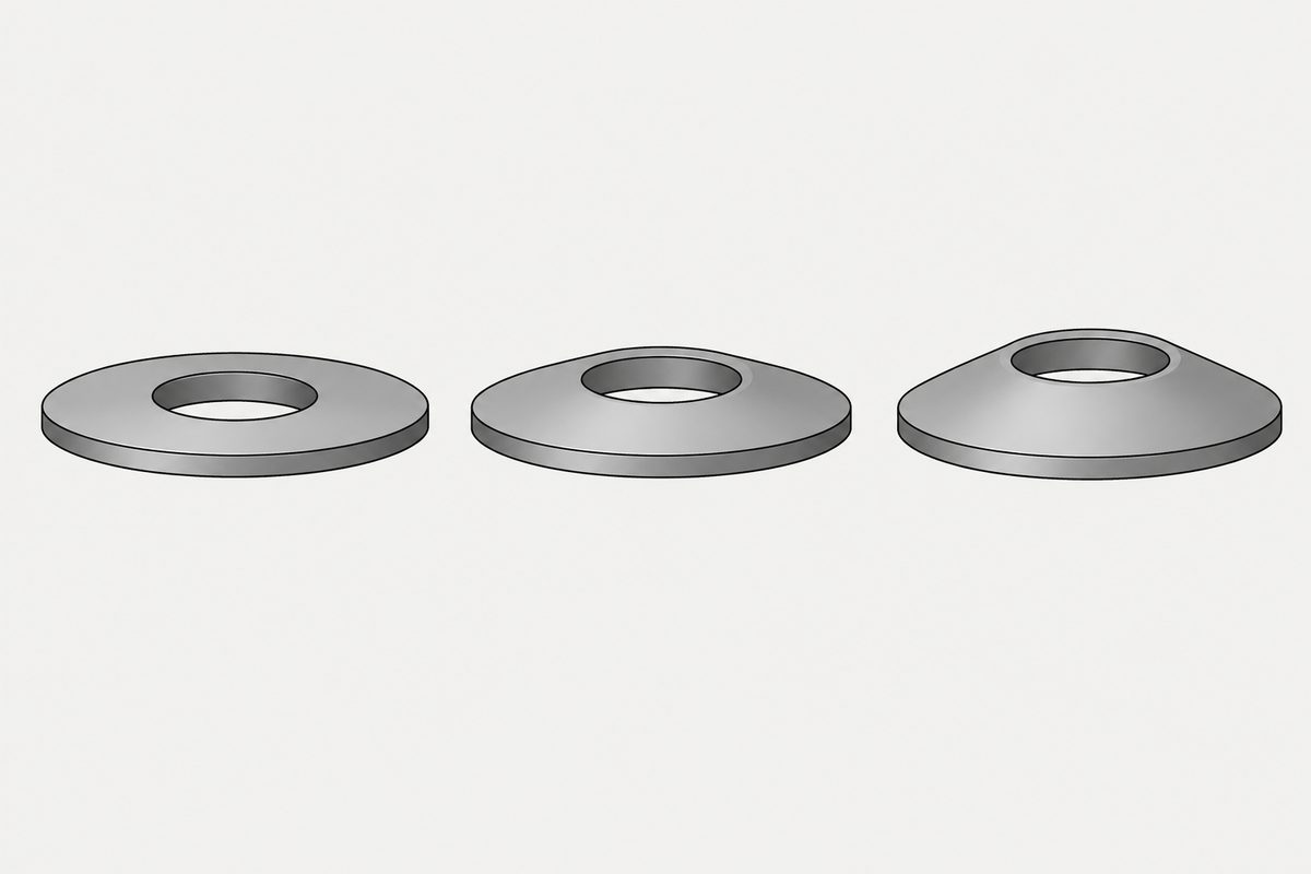
The letter is a ratio
A disc spring is a cone. Two dimensions describe how much of a cone it is: h0, the free deflection height, and t, the material thickness. The ratio between them is what the series letter records. Schnorr, whose handbook lists sizes to DIN 2093, puts it plainly in its notes on the table:
The prefix A, B or C shows the corresponding series.
And the three series sit at different values of that ratio:
| Series | h0/t | What the disc is like |
|---|---|---|
| A | about 0.40 | thick for its cone height |
| B | about 0.75 | in between |
| C | about 1.30 | thin for its cone height |
The three are formally dimensional series, separated by proportions rather than by a rating: outside diameter to thickness, and cone height to thickness. So the letter is not a strength grade in the way 8.8 and 10.9 are on a bolt. Nothing about A, B or C says one is stronger. What changes is the shape of the curve, and that is a property you choose rather than one you rank.
Specifying by ratio carries a cost, and it shows up first at small sizes. On a small disc h0 and t are both small numbers, and a ratio between two small numbers is what manufacturing tolerance moves first — while the handbook’s own thickness tolerance table grows proportionally coarser as the disc gets thinner. The ratio that defines the curve is held least tightly where the disc is thinnest.
What the ratio buys you
The reason anyone specifies that ratio is the shape of the load-deflection curve. Schnorr’s technical page states the range available:
Linear, degressive or even progressive design of characteristic lines.
A second manufacturer, MW Components, sets out how the single-disc curve moves as the ratio rises, and its catalogue arranges the cases as a ladder:
| h/t | Curve |
|---|---|
| below 0.4 | approximately linear |
| about 1 | regressive — flattening as it compresses |
| 1.4 | constant load |
| above 1.4 | negative type |
The same catalogue states the small-ratio end directly: when the ratio is small, up to 0.4, the shape approximates a straight line. Read the ladder against the series values and series C, at about 1.30, sits just under the constant-load point. That is our reading of two sources side by side rather than a statement either of them makes.
One entry does not belong to the ladder. MW lists progressive curves too, and sends the reader to a different page for them, because a progressive characteristic comes from stacking discs of differing thickness or differing parallel counts rather than from the ratio of a single disc. Schnorr’s “linear, degressive or even progressive” describes what can be designed with disc springs, not what one disc does on its own.
The flattening one is why a disc spring turns up in a bolted joint at all. What a joint loses to embedding and settling is a small amount of length, and an ordinary stiff joint answers a small loss of length with a large loss of preload. A spring whose force barely changes over that range answers it with almost none. That is the job, and it is a different job from stopping a fastener rotating. Our washer specification page makes the same distinction from the washer side.
The numbers in the table are calculated
This is the sentence worth taking away, and it is in the notes beside the table rather than in the table:
The load and the corresponding stresses are given for the three points s = 0.25 ho, s = 0.5 ho, s = 0.75 ho. From s > 0.75 ho, the actual characteristic curve increases progressively, contrary to the calculation (the table contains calculated values).
Three things are being said at once. The tabulated values exist at three deflection points and nowhere else. They are calculated rather than measured. And past three quarters of the available travel, the real spring departs from the calculation in a stated direction: it gets stiffer than the table says.
The direction matters more than it first appears. A designer running out of room tends to push a spring toward flat, and that is exactly the region where the table stops describing the part and starts underestimating the force it will produce. The manufacturer says so on the same page as the numbers. It is the kind of note that gets skipped because it sits outside the grid, next to a table that looks self-sufficient.
MW Components draws the working conclusion from the same fact: disc springs should be designed to work within 20% to 80% of their total available deflection. Put the two statements together and the recommended range stops at 80% while the calculated table stops describing the spring at 75%. Its catalogue also carries a section titled “Theoretical vs. Measured Characteristic of a Disc Spring”, which is a second manufacturer devoting a heading to the gap this page is about.
Stacking changes which quantity adds
One disc rarely gives both the force and the travel a design needs, so discs are stacked. The two ways of stacking add different quantities:
| Arrangement | What adds | What stays put |
|---|---|---|
| In series (alternating) | deflection | load |
| In parallel (nested) | load | deflection |
Schnorr states both: in series, “the spring deflections add up with constant load”; in parallel, “the forces add up at the same deflection”. So the stack is a second design variable sitting on top of the series letter, and a column of discs is really two decisions, the disc and the arrangement.
Parallel stacking carries a caution from the same handbook. Some discs are made with turned bearing surfaces and a reduced thickness t′, and Schnorr notes that t′ is the effective thickness that “must be accounted for with parallel stacking for determining the column length”. Stack length is not simply the count times the nominal thickness.
The number on the drawing has changed
Almost everything written about disc springs, in any language, cites DIN 2093 for dimensions and DIN 2092 for calculation. Schnorr’s own technical page records that both were replaced on 1 February 2017 by DIN EN 16983 for dimensions and quality requirements and DIN EN 16984 for calculation, with the technical content unchanged.
Unchanged content is why nothing breaks and also why nobody updates. A part bought to DIN 2093 is the same part; a drawing that still cites DIN 2093 is citing a number that has been superseded for years. If a drawing is being reissued anyway, that is the moment the reference is cheap to fix.
What this page did not establish
- No standard was read. DIN 2092, DIN 2093, EN 16983 and EN 16984 are all paid documents. The series-to-ratio correspondence, the replacement and its date come from Schnorr’s own published material, which is a manufacturer’s statement about standards rather than the standards.
- No load or stress values appear here. The handbook carries full tables; this page quotes only its explanatory text. Values depend on size, series and material, and reproducing them without the surrounding conditions would be the mistake this page is about.
- DIN 6796 is a different standard. It covers conical spring washers for bolted joints, not disc springs to DIN 2093. Our page on trading torque control for length control describes DIN 6796 from summaries it flags as unverified, and this page does not settle that: a similar shape under a different standard is not the same part.
- The ratio ladder is theory for a single disc. The values above describe a single disc of standard geometry. They are not a promise that a particular part reverses at exactly 1.414, and a stack behaves as a stack rather than as its discs.
- Friction in parallel stacks is not quantified here. A cross-check reported a design allowance of roughly 2 to 3% of the force per sliding surface, added on loading and subtracted on unloading. The source we were pointed to returned a 403 to us, so it is recorded as a lead rather than a figure to use.
- Nothing here is about fatigue or cycling. The three tabulated points and the note about the real curve are static. Disc springs in cyclic service have their own limits that this page does not cover.
This is not one of the six steps. It shows up across them, or after assembly. Where the decisions that lead here were made is in specifying a screw, which sets out the order and why doing it out of order is rework.
Common questions
What do A, B and C mean on a disc spring?
They are dimensional series, separated by proportions rather than by a rating. One of those proportions is h0/t, the ratio of free cone height to material thickness, and Schnorr lists the three series at roughly 0.40 for A, 0.75 for B and 1.30 for C. That ratio sets the shape of the load-deflection curve, so the letter is not a strength grade in the way 8.8 and 10.9 are on a bolt: nothing about A, B or C says one is stronger.
Why does the h0/t ratio matter?
Because it sets the shape of the curve for a single disc. MW Components arranges the cases as a ladder: below 0.4 the curve is approximately linear, around 1 it is regressive, at 1.4 it is constant load, and above 1.4 it is a negative type. A flattening curve changes force little across a range of movement, which is what makes a disc spring useful against preload lost to embedding and settling. Progressive curves are a separate case that comes from stacking rather than from one disc’s ratio.
Are the catalogue load values measured?
No. Schnorr states that the load and corresponding stresses are given for three points, s = 0.25 h0, s = 0.5 h0 and s = 0.75 h0, and that from s greater than 0.75 h0 the actual characteristic curve increases progressively, contrary to the calculation, because the table contains calculated values. Past three quarters of travel the real spring is stiffer than the table.
What is the difference between stacking in series and in parallel?
In series, alternating discs, the deflections add and the load stays constant. In parallel, nested discs, the forces add at the same deflection. Schnorr states both. Note also that discs with turned bearing surfaces have a reduced effective thickness t′, which must be used when working out the length of a parallel stack.
Is DIN 2093 still the right standard to cite?
Schnorr records that DIN EN 16983, for dimensions and quality requirements, and DIN EN 16984, for calculation, replaced DIN 2093 and DIN 2092 on 1 February 2017, with the technical content unchanged. The part is the same part, so nothing breaks, but a drawing still citing DIN 2093 is citing a superseded number.
Is a disc spring a locking device?
No. It maintains preload against losses of length, from embedding, settling and thermal cycling. Preventing a fastener from rotating is a different problem with different answers, and a spring that holds load is not the same as a device that resists rotation.
References
- Schnorr, disc spring product data — the notes on the disc spring table: the A/B/C prefix, the three calculated deflection points, the behaviour past 0.75 h0, and the effective thickness t′ for parallel stacks (free PDF)
- Schnorr, Disc Springs — the h0/t values for series A, B and C, the linear/degressive/progressive range, series and parallel stacking, and the replacement of DIN 2092 and DIN 2093 by DIN EN 16984 and DIN EN 16983 on 1 February 2017
- MW Components, Disc Springs catalog — the h/t ladder (linear below 0.4, regressive about 1, constant load at 1.4, negative type above 1.4), the 20%–80% working range, and the section headed “Theoretical vs. Measured Characteristic of a Disc Spring” (free PDF)
- DIN EN 16983, Disc springs — quality specifications, dimensions; catalogue entry only, the standard was not read
- DIN EN 16984, Disc springs — calculation; catalogue entry only, the standard was not read
Three manufacturer documents were opened and read directly — the two Schnorr sources from schnorr.com and schnorr-group.com, and the MW Components catalog PDF, which was converted with pdftotext and searched for its h/t discussion — and every quotation on this page is taken from them: the product data PDF was converted with pdftotext and the notes beside the disc spring table were read in full. They are a manufacturer’s published material, which means the statements about what DIN 2093 contains, and about EN 16983 and EN 16984 replacing it, are a manufacturer reporting on standards rather than the standards themselves. None of DIN 2092, DIN 2093, EN 16983 or EN 16984 was read; all four are paid documents. No load, stress or dimensional value from the handbook tables appears here — only its explanatory text — because the point of this page is that those values carry conditions, and reproducing them without the conditions would repeat the error. DIN 6796 is named only to separate it from DIN 2093; the description of DIN 6796 on our torque-into-length page remains flagged there as unverified and is not settled here.
Enquiries
If a joint is losing preload rather than rotating loose, the useful things to tell us are how much length it is losing and to what — embedding, a gasket, thermal cycling. The answer to each is a different part, and only one of them is a spring.
Request a quotation
Tell us the part and the quantity. We will come back on feasibility, lead time and price.
Or email us directly sales@tigerfasteners.com