 TIGERFASTENERS
A Heat-Set Insert Displaces a Volume, and the Hole Is Where It Goes
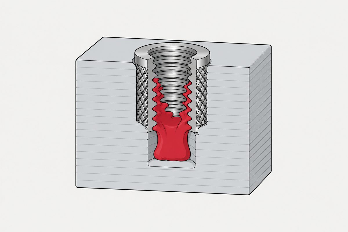
Somebody on r/3Dprinting kept getting molten plastic climbing into the threads of his heat-set inserts. PETG, iron at 215 °C, a half-degree chamfer on both sides of the hole, and the sensible-sounding question at the end: should he just make the chamfer huge? The thread gave him two good answers that fix two different things, and it is worth separating them, because the arithmetic behind the second one lands on the number he eventually found by trial.
Two corrections, and they are not the same correction
The most-upvoted reply is four words long: make the hole larger. The second, at 356 points, says something different: run a hole-accuracy calibration, save it in the slicer, and do it for every filament, because the result for PLA will not be the result for PETG.
Those two are fixing separate problems that happen to land on the same dimension.
| Correction | What is wrong | Who owns it |
|---|---|---|
| Calibration | The printed hole is not the hole in the CAD model | The printer and the filament |
| Clearance | Even a perfect hole is smaller than the insert, and the difference is a volume of polymer that has to go somewhere | The insert |
They add up, and if you only fix one you spend a long time chasing the other. The poster ended up doing both without quite naming them: he took the holes up 0,5 mm in CAD, found that PETG shrinkage was worse than he expected, and then added another 0,3 mm.
The arithmetic nobody in the thread does
A heat-set insert is a solid brass body pushed into a hole that is smaller than it is. Polymer is not destroyed by that, only moved. The volume displaced is the annulus between the two diameters, over the length of engagement:
V = (π/4) × (dinsert² − dhole²) × L
Take a common M3 insert. Vendor catalogues put this size at roughly 4,6 mm outside diameter and 5,7 mm long, with an M3 thread whose minor diameter is about 2,5 mm, giving a bore cross-section of 4,91 mm². If the displaced polymer goes up that bore, which is exactly the symptom being complained about, here is how far it climbs:
| Hole ø | Displaced | Climb up the bore | As a share of the insert |
|---|---|---|---|
| 3,8 mm | 30,1 mm³ | 6,1 mm | 108 % |
| 4,0 mm | 23,1 mm³ | 4,7 mm | 83 % |
| 4,2 mm | 15,8 mm³ | 3,2 mm | 56 % |
| 4,3 mm | 12,0 mm³ | 2,4 mm | 43 % |
| 4,5 mm | 4,1 mm³ | 0,8 mm | 15 % |
At 3,8 mm there is more surplus polymer than there is bore to hold it. That is not a threshold anyone has to discover experimentally; it falls out of two diameters and a length.
And the last two hundred points of the thread are in one line of that table. Going from 4,0 to 4,3 mm, the +0,3 mm the poster added, cuts the displaced volume from 23,1 to 12,0 mm³. It halves it. He found that by trial. The arithmetic gets there from the catalogue dimensions.
So make the chamfer huge, and here is how huge
The question at the end of his post deserves a real answer rather than a no. A chamfer genuinely is a place for surplus material to sit. The problem is how much it holds, which is a ring of revolution and therefore small:
| Chamfer on a 4,0 mm hole | Volume it can hold | Share of a 23 mm³ surplus |
|---|---|---|
| 0,5° × 0,5 mm | 0,01 mm³ | 0,04 % |
| 45° × 0,5 mm | 1,70 mm³ | 7 % |
| 45° × 1,0 mm | 7,33 mm³ | 32 % |
The chamfer he had is three orders of magnitude smaller than the volume it would have to absorb. A half-degree chamfer is a lead-in, and a lead-in is a useful thing, but it is not a reservoir. Even a proper 45° by 1 mm chamfer, which is large on a 4 mm hole, takes about a third of the surplus. So yes, make it bigger, and no, it is not the lever. The hole diameter is the only term in the equation that moves the surplus itself rather than finding somewhere to park it.
Why this number is an upper bound
The calculation above says the surplus is larger than it really is, for three reasons worth knowing because two of them are specific to printed parts.
- The insert is not a cylinder. Knurls, undercuts and tapers mean the real body displaces less than the full annulus between the two diameters
- A printed part is not solid. Between the walls and the infill there is void, and softened polymer is pushed into it. A moulded boss has nowhere comparable to put the surplus, which is why printed parts tolerate a tighter hole than a catalogue written for injection moulding suggests
- The melt compacts. Some of the volume disappears into density rather than moving
None of that changes the direction of the argument, only the size of the correction. It does mean that copying a moulded-boss hole table into a printed part is the wrong starting point in a way people do not expect, since the printed part usually wants less clearance rather than more.
What we could and could not find in the way of a standard
Hole sizes for heat-set inserts come from vendor catalogues, and they vary by resin, by fill and by insert profile. Manufacturers cite DIN 16903 for inserts in plastics, and a search indicates at least the R type of that standard has been withdrawn. We did not read it, so nothing on this page is quoted from it, and no vendor hole table is reproduced here either. The point of the arithmetic above is that it lets you sanity-check whichever table you are handed, in the units the table is silent about.
The other half of the decision is what the insert is doing once it is in. What each insert family assumes about the parent, and the installation target for a heat-set insert in particular, is when the parent cannot be the nut. Why a thread formed directly in plastic behaves the way it does, and why the torque window is the specification rather than a single value, is screws into plastic. And the reason a printed boss is a harder case than a moulded one is that the insert loads it in hoop, straight across the layer lines, which is the weak direction of the part.
This page covers step 1, the substrate. The whole order is substrate, thread, head, drive, finish, documentation, and why doing it out of order is rework rather than a tweak is in specifying a screw.
Common questions
Why does plastic climb into the threads of a heat-set insert?
Because the insert displaces a volume of polymer and that volume has to go somewhere. For a common M3 insert of about 4,6 mm outside diameter and 5,7 mm long, a 4,0 mm hole leaves roughly 23 cubic millimetres of surplus. The bore of an M3 insert has a cross-section near 4,9 square millimetres, so if the surplus travels up the bore it climbs about 4,7 mm, which is 83 per cent of the insert length. At a 3,8 mm hole there is more surplus than bore.
Will a bigger chamfer fix it?
It helps and it is not the lever. A chamfer is a ring of revolution, so it holds much less than people picture. On a 4,0 mm hole, a 0,5 degree by 0,5 mm chamfer holds about 0,01 cubic millimetres against a surplus near 23. Even a 45 degree by 1 mm chamfer, which is large for that hole, takes about a third. The hole diameter is the only term that reduces the surplus rather than parking it.
How much bigger should the hole be?
That comes from the insert vendor and it varies with resin, fill and insert profile, so this page does not publish a figure. What the arithmetic gives you is a way to check any figure you are given: work out the displaced volume for the hole you are considering and ask where it is meant to go. On the source thread the poster ended up adding 0,3 mm to holes he had already enlarged, and that step alone halves the displaced volume.
Why did the same hole work in PLA and not in PETG?
Two effects stack. The printed hole is not the hole in the CAD model, and the difference depends on the material, which is why the second-highest answer on that thread recommends a hole-accuracy calibration saved per filament. On top of that the insert still displaces the same volume for a given finished hole size. The poster hit both: he found PETG shrinkage worse than expected and then needed more clearance on top.
Can I use an injection-moulding boss table for a printed part?
It is the wrong starting point, and usually in the direction people do not expect. A printed part has void between the walls and the infill for softened polymer to be pushed into, which a moulded boss does not, so a printed part often tolerates a tighter hole than a moulded table suggests rather than a looser one. Treat the table as a first guess and check it against the displaced volume.
References
- r/3Dprinting — the thread this began in, including the poster’s own update about PETG shrinkage and the two highest-voted answers
- r/3Dprinting — is anything better than heat staking a threaded insert; cited here only as evidence of how often the question is asked
The displaced-volume arithmetic on this page is our own and can be repeated from two diameters and a length. The insert dimensions used in the worked example, roughly 4,6 mm outside diameter and 5,7 mm long for an M3, are typical vendor catalogue dimensions rather than a standard, and a different vendor’s insert will give different numbers; the arithmetic is the transferable part, not the table. The calculation is an upper bound, for the three reasons set out above. No hole size is recommended here, because that belongs to the insert supplier and varies with resin, fill and insert profile. Manufacturers cite DIN 16903 for inserts in plastics and a search indicates at least its R type is withdrawn; we did not read that standard and nothing here is quoted from it, and we found no ISO standard covering heat-set insert boss dimensions. The most-upvoted reply on the source thread points at a well-known experimental video series on this subject; we have not read its underlying data and quote no figure from it. We also found no published measurement of pull-out strength for heat-set inserts in printed parts that we were willing to cite, so this page makes no strength claim.
Enquiries
If an enquiry involves inserts into plastic, tell us the resin and whether the part is moulded or printed. Those are different problems: a moulded boss has nowhere to put displaced material and a printed one does, and the hole that works in one is not the hole that works in the other.
Request a quotation
Tell us the part and the quantity. We will come back on feasibility, lead time and price.
Or email us directly sales@tigerfasteners.com