 TIGERFASTENERS
A retaining ring’s thrust rating is the lower of two numbers
Read about seven minutes. A retaining ring catalogue gives you a thrust load in pounds or newtons, printed next to the part number where a strength figure would go. It is not the strength of that part. It is the smaller of two calculations, one of which is about a groove you machined yourself, and both of which assume a corner geometry worth checking before you rely on the number.
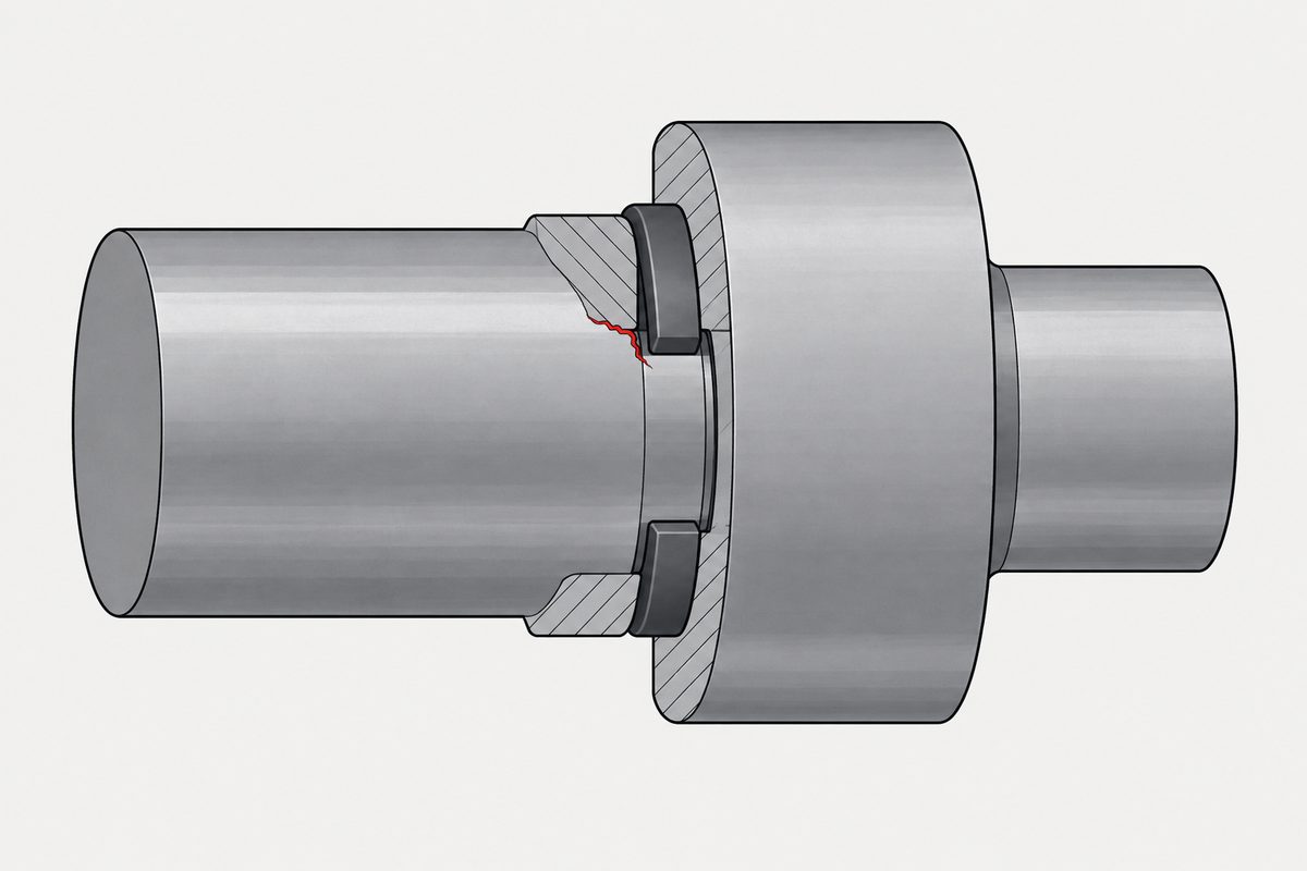
One number on the page, two calculations behind it
Ring manufacturers publish the same pair of calculations. Smalley states them as:
| What fails | Formula | Safety factor |
|---|---|---|
| Ring shears | PR = (π × D × T × SS) / K | K = 3 |
| Groove deforms | PG = (π × D × d × SY) / K | K = 2 |
D is the shaft or housing diameter, T the ring thickness, SS the shear strength of the ring material, d the groove depth, and SY the yield strength of the groove material. The design value is the lesser of the two.
Rotor Clip publishes the same structure with an extra term: a conversion factor Gf, taken from a table, sits in both expressions. So the two are not the same formula written twice. They agree on what governs and differ in what they carry, which is worth knowing before setting one company’s output against another’s.
Look at what each formula contains. The first is about the ring: its thickness, its material. The second contains nothing about the ring at all. Its two variables are the depth of the groove and the yield strength of the material the groove was cut into, which are both yours.
Which one usually wins
Smalley answers this directly:
Groove deformation is by far the most common design limitation of retaining rings.
So the part that limits the assembly is normally not the part you bought. It is the groove, and the groove is a feature on your shaft or in your housing, cut to your depth, in your material. A ring in a shallow groove in a soft shaft has a low capacity, and nothing about that shows up in the ring’s part number.
This is a recurring shape. The rated component carries a number, the mating feature carries the actual limit, and only one of them is on a purchase order. It is the same reason only one kind of pin has a rated shear value, and the same reason a working load limit is an authorisation rather than a prediction.
The number assumes a corner
Rotor Clip states the assumption behind every tabulated value:
All of the formulas above and the values for Pr given in the data charts for each ring type are calculated for assemblies in which the retained parts have square corners.
A square corner puts the load into the ring right at the groove, where the ring is supported. Move the contact outward and the ring is loaded further from its support, so it begins to dish out of the groove instead of shearing in place. A chamfer on the retained part does that. So does a radius.
The sentence that follows is the one that catches people, because it turns a clearance into a geometry error:
When there is radial play between the retained part and the shaft or housing, such play must be treated as though the retained part had a chamfered corner.
A retained part with a perfectly square corner, but a loose fit on the shaft, is not a square-corner assembly. The play is an equivalent chamfer, and it counts against the rating in the same way. That condition is invisible on the drawing of either part, and it lives in the fit between them.
The safety factor is not settled
Three published sources give the same two calculations and do not agree on what to divide by:
| Source | Ring shear | Groove yield |
|---|---|---|
| Smalley | 3 | 2 |
| Rotor Clip | 4 | 2 |
| Engineers Edge | 3 | 2 |
The groove column agrees. The ring column does not, and the gap is not decorative. For the same inputs, dividing by 4 instead of 3 gives an allowable thrust 25% lower — that is our arithmetic, 3 ÷ 4 = 0.75, and it is a property of the safety factor rather than of anyone’s ring.
The practical consequence is about comparison. Two catalogue thrust figures from two manufacturers are not necessarily on the same basis, so a difference between them may be a difference in what each chose to divide by. If a selection turns on that comparison, the thing to ask each supplier is which factor is already inside the printed number.
One further inconsistency is worth recording without explaining it. The Engineers Edge page states a factor of 3 for ring shear in its text, while a footnote under its table reads “Thrust Load Safety Factors: Ring, 1; groove, 2”. Those do not match. We do not know which reading is intended and are not guessing.
A cross-check of this page suggested that Rotor Clip applies different factors to different ring types, 4 to tapered-section rings and 3 to spiral ones. We read the page twice and got the same answer both times: 4 for the ring and 2 for the groove, with no distinction drawn by type. The table above reports what we read. That the question is open at all is part of the point.
What the standard is said to do
DIN 471 covers retaining rings for shafts and the grooves they sit in. Standards summaries and supplier descriptions say it splits the capacity the same way the manufacturers do: FN for the groove, evaluated at a yield point of 200 MPa for the grooved material, and FR for the ring itself with a sharp-edged abutment.
If that description is right, the fixed 200 MPa is worth noticing, because it means a tabulated groove capacity is tied to an assumed material strength rather than to yours. A cross-check went further and reported that the standard’s method scales linearly off that basis, so a different groove material is handled by conversion rather than by the table being wrong. We could not confirm that: the technical sheet cited for it returned a 403 to us. It is recorded here as a lead. DIN 471 is a paid document and we did not read it.
What this page did not establish
- No thrust values appear here. We hold no manufacturer data tables, and the values depend on ring type, material and size. This page carries the formulas and the structure, not numbers to design against.
- No standard was read. DIN 471 and DIN 472 are paid documents. Full copies circulate on file-sharing sites; we did not download or cite one. What is attributed to DIN 471 here comes from summaries and supplier material and is flagged in the text.
- No reduction figure for chamfers. Rotor Clip publishes an adjustment for chamfers and radii below the maximum allowable, and a worked example alongside it. We read that page twice and came away with two different worked examples, so we are not quoting either. The direction is stated on this page; the magnitude is not, and a number we cannot reproduce on a second reading is not a number to publish.
- “Most common” is not “always”. Smalley calls groove deformation the most common design limitation. A hard groove in a hardened shaft with a thin ring can invert that, which is what running both calculations is for.
- Static thrust only, and the source says so too. Everything above is about axial load pushing a retained part against a ring. Rotor Clip states that sudden loads should not exceed 50% of the allowable static thrust load, whichever of Pr or Pg is lower, and gives relative rotation its own separate limit, Prr ≤ (s t E²) / (μ 18 Ds). A static rating is not a dynamic one, and the manufacturers do not treat it as one either.
Why this matters more as things get smaller
Groove depth is the variable the groove formula is most exposed to, and it is the one that gets squeezed first on a small shaft. On a large shaft a groove is a rounding error in the cross-section; on a small one it is a visible fraction of the remaining diameter, so the depth that the capacity wants and the depth the shaft can spare pull in opposite directions. Nothing in the ring catalogue mediates that, because the catalogue describes the ring and it is the groove that gets squeezed. Which is this page from end to end: of the two calculations, the one that wins is not on your purchase order.
This is not one of the six steps. It shows up across them, or after assembly. Where the decisions that lead here were made is in specifying a screw, which sets out the order and why doing it out of order is rework.
Common questions
What thrust load can a retaining ring take?
It is the lower of two calculated values, not a single property of the ring. Manufacturers publish a ring shear capacity, PR = (π × D × T × SS) / K, and a groove capacity, PG = (π × D × d × SY) / K, where D is the shaft or housing diameter, T the ring thickness, SS the shear strength of the ring material, d the groove depth and SY the yield strength of the groove material. The design value is whichever is smaller.
Which fails first, the ring or the groove?
Smalley states that groove deformation is by far the most common design limitation of retaining rings. That means the limit usually sits in a feature you machined, defined by your groove depth and your material, rather than in the part you purchased. It is not a rule, though. Both calculations exist because either can govern.
Does a chamfer on the retained part matter?
Yes, and so does a loose fit. Rotor Clip states that all its formulas and tabulated Pr values are calculated for assemblies in which the retained parts have square corners, and that radial play between the retained part and the shaft or housing must be treated as though the part had a chamfered corner of that magnitude. A square-cornered part with a sloppy fit is not a square-corner assembly.
Why do two manufacturers give different capacities for a similar ring?
Partly because the safety factor is not standardised. Smalley recommends dividing the ring shear result by 3, Rotor Clip by 4, while both use 2 on the groove. For the same inputs, dividing by 4 rather than 3 yields an allowable thrust 25% lower. Before comparing two catalogue figures, ask each supplier which factor is already inside the printed number.
Is a retaining ring a locking device?
No. It is an axial location feature: it holds a part in position against thrust along the axis. It does not maintain preload and it is not a thread-locking method. The failure modes discussed here are the ring shearing or the groove deforming, both under axial load.
Does DIN 471 give load capacities?
Standards summaries and supplier descriptions say it does, splitting them into FN for the groove, evaluated at a yield point of 200 MPa for the grooved material, and FR for the ring with a sharp-edged abutment. We have not read DIN 471; it is a paid document, and the fixed 200 MPa in that description would mean a tabulated groove value is tied to an assumed material rather than to the one you are cutting.
References
- Smalley, Load Capacity — the ring shear and groove deformation formulas with symbol definitions, the recommended safety factors, and the statement that groove deformation is the most common design limitation
- Rotor Clip, Formulas: Retaining Ring Load Capacity — the same formula pair, the square-corner assumption behind the data charts, and the rule that radial play is treated as a chamfer
- Engineers Edge, Thrust Load Capacity — a third statement of the safety factors, and the table footnote that does not match its own text
- DIN 471, Retaining rings for shafts — catalogue entry only; the standard itself was not read
The three engineering references were read directly from the pages linked above, and the formulas, symbol definitions, safety factors and the two quoted assumptions are taken from them. They are manufacturer and reference material rather than standards. DIN 471 and DIN 472 were not read: both are paid documents, and although full copies of DIN 471 circulate on file-sharing sites, we did not download, read or cite one — what is attributed to DIN 471 on this page comes from summaries and supplier descriptions and is marked as such in the body. The only arithmetic here is ours: for identical inputs the ratio between a safety factor of 3 and one of 4 is 3 ÷ 4 = 0.75, so the stricter factor gives an allowable thrust 25% lower. No thrust values are published on this page, because we hold no manufacturer data tables and the tabulated values depend on ring type, material and size.
Enquiries
If an assembly locates a part axially and you are not sure whether the ring or the groove is the limit, the two numbers to send are the groove depth and the shaft material. Those decide more than the ring part number does.
Request a quotation
Tell us the part and the quantity. We will come back on feasibility, lead time and price.
Or email us directly sales@tigerfasteners.com