 TIGERFASTENERS
Taring a Preloaded Load Cell Removes the Offset and Leaves a Gain Error
An office argument reached an engineering forum this week. A load cell sits between two brackets that are bolted together and torqued to a preload of a hundred pounds. Apply fifty pounds on top. One camp says the cell still reads a hundred, because the applied load has to overcome the preload first. The other says it reads a hundred and fifty, because loads add. Thirty five comments later the thread had the right mechanism and no arithmetic, so here is the arithmetic, and then a second document that most of the argument would have been settled by.
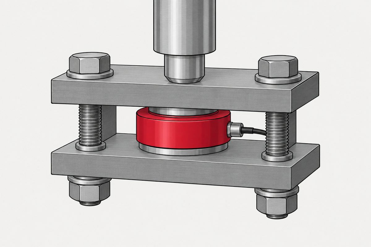
Neither number. The load cell and the bolts are two springs in parallel between the same two brackets, and parallel springs share every load from the first pound. There is no dead band. The reading is the preload plus the clamped member’s share of the applied load, and the error against the true applied load is Fi minus ΦP, which starts at the preload and falls to zero when the bolts go slack. Taring at zero load removes the constant and leaves the slope, so after taring you read low by Φ across the whole working range.
The arithmetic in that paragraph is ours, and the rest of this page shows it. It rests on the model this site has already set out in the bolt is a spring, and so is the joint, which is where the symbol Φ and its two competing conventions are explained. Nothing below re-derives that.
The geometry, because the answer changes sign with it
The drawing that came with the question shows a top plate, four bolts running down through it into a base, and the load cell as a cylinder squeezed between the plate and the base. The arrow labelled applied load points down onto the top plate.
That matters more than anything else in the problem. Pushing down squeezes the cell harder and relieves the bolts. Pulling up would do the opposite. Both answers appear in the thread, and part of the disagreement there is simply that people pictured different directions. Everything below is the pushing case.
The arithmetic
Write kb for the stiffness of the bolts and kc for the stiffness of what they clamp, which here is the load cell in series with the brackets. Following the convention on the earlier page, Φ = kb / (kb + kc) is the share of an external load that lands on the bolt, and the clamped side takes the remainder, 1 − Φ.
Push down with P. The stack shortens by P divided by the sum of the two stiffnesses. The cell picks up (1 − Φ)P of extra compression and the bolts shed ΦP of tension. So, with Fi for the preload:
Reading = Fi + (1 − Φ)P, until the bolts run out of tension. That happens at ΦP = Fi, so at P = Fi / Φ. Above it the cell carries everything and the reading is simply P.
Put the thread’s numbers in. A hundred pounds of preload, fifty pounds pushed on top. The three rows below are illustrations, not measurements of any real cell, and the stiffness ratio is the thing you would have to get from the manufacturer.
| kc / kb | Φ | Reading at P = 50 lb | Bolts go slack at |
|---|---|---|---|
| 4, a stiff cell | 0,2 | 140 lb | 500 lb |
| 1, equal | 0,5 | 125 lb | 200 lb |
| 0,25, a soft cell | 0,8 | 110 lb | 125 lb |
Never a hundred, never a hundred and fifty. And the number does not sit halfway between the two camps by accident, it moves with the stiffness ratio, which is what several people in the thread were pointing at when they said it depends.
One check on the algebra. At the load where the bolts go slack, the formula gives Fi + (1 − Φ)Fi/Φ, which simplifies to Fi/Φ, which is the applied load itself. The two branches meet, as they have to, and from there the cell tracks the load one for one.
The error, and what taring does to it
Subtract the true applied load from the reading and almost everything cancels.
Error = Fi − ΦP
It is a straight line. At zero load the cell over-reads by the whole preload, which is what the taring step is for. As the load rises, the error shrinks, and it reaches exactly zero at P = Fi/Φ, the same place the bolts go slack. Beyond that the preload has vanished from the reading entirely.
So the preload does not cost you a fixed slice of range. It distorts the bottom of the range and the distortion decays. That is a different failure than either camp was arguing about.
Now tare. Zeroing at P = 0 subtracts Fi, and what is left is
Tared reading = (1 − Φ)P
The offset is gone and a gain error of Φ remains. With a stiffness ratio of four you read twenty per cent low, everywhere, in a way that looks perfectly linear and perfectly repeatable and will pass any check that does not involve a known weight. The fix is not a better tare. It is either a gain correction of 1/(1 − Φ) or, more honestly, calibrating the cell in the fixture it will live in.
That is also why the thread’s one experimental report, that the preload shifted the bias but not the slope in millivolts per pound, is consistent rather than contradictory. That test had the bolts outside the measured path. Put them in parallel with the sensing element and the slope is exactly what changes.
Where the threshold intuition comes from
The idea that nothing happens until the applied load exceeds the preload is not a silly one. It is correct, for a different structure. A spring held down against a stop really does stay put until you overcome its preload, because the stop can let go. A motorbike suspension with preload on the spring behaves that way, and somebody in the thread reached for exactly that comparison.
The difference is a gap. In the suspension the preloaded spring is in series with something that can separate. In the bolted stack the load cell is in parallel with the bolts, touching both brackets at all times, and nothing can separate until the joint opens. Parallel springs share. Series with a stop has a threshold. Deciding which one you are looking at settles the argument without any numbers at all.
Pull up instead of pushing down and a threshold does appear, at the far end. The reading then falls, as Fi − (1 − Φ)P, and the joint opens at P = Fi/(1 − Φ), after which the cell reads zero and sees nothing at all. So there is a load above which you go blind, and it is not the preload, it is the preload divided by the clamped share.
The other half of the question has its own standard
The person asking wanted to settle a taring procedure and find out whether they had lost measuring range. Both of those have a vocabulary, and it is not in any fastener document. It is in OIML R 60-1:2021, Metrological regulation for load cells, part 1: metrological and technical requirements, which the International Organization of Legal Metrology publishes as a free PDF, along with its part 2 on tests. That edition was approved for publication at the 56th meeting of the International Committee of Legal Metrology in October 2021 and supersedes the 2017 edition.
It is a legal metrology recommendation, written for cells that end up inside trade weighing instruments, so it does not govern somebody’s test fixture. We are reading it for its definitions and, more usefully, for the conditions under which a cell’s numbers were demonstrated in the first place.
The first thing it gives you is the name for what the bolts are doing. Dead load. The standard defines a minimum dead load, Emin, as the smallest quantity that may be applied to a load cell, and it defines the maximum measuring range as Emax minus Emin. A preload sitting permanently in the clamp path is dead load, and it eats that range from the bottom.
The tenth of capacity
Then comes a pair of inequalities that is worth pinning to the wall. The standard separates the parameters fixed by the design of the cell, Emin and Emax, from the ones that vary with the test, Dmin and Dmax, and then bounds the second pair by the first.
“a) (Dmax − Dmin) ≤ (Emax −
Emin)”
“b) Emin ≤ Dmin ≤ (0.1
Emax), and (0.9 Emax) ≤ Dmax ≤
Emax”
Read the left half of b. Every error limit in the recommendation is demonstrated with the bottom of the tested range at no more than a tenth of capacity. Bolt a hundred pounds of preload through a cell rated for two hundred and the working zero sits at half of capacity. Whatever the data sheet says the cell can do, it was not shown to do it starting from there.
The other bound is the one to check before torquing anything. The safe load limit, Elim, is defined as the maximum load that can be applied without producing a permanent shift in the performance characteristics beyond those specified. Preload plus working load has to stay under it, and preload is there whether or not anybody is testing that day.
The standard already uses the word preload, for something else
This one is a small pleasure. Open part 2 at the test procedures and step three of nearly every test is headed Preload load cell. It does not mean what a fastener engineer means.
“Preload the load cell by applying the maximum test load, Dmax, three times, returning to the minimum test load, Dmin, after each load application. Wait 5 minutes before commencing with further tests.”
Three exercise cycles to full load, then a wait. For the creep and zero return tests the same step ends wait one hour instead. So the two professions in that office argument were using one word for two different things, one of them a standing bolt tension and the other a warm-up routine, which is a decent share of how the conversation went sideways.
Creep and zero return are qualified over half an hour
The taring question has a second edge that the thread never reached. A cell in a bolted fixture is under load permanently. The standard defines creep as change in output occurring with time while under constant load and everything else held steady, which is precisely the condition a preload creates, and it puts limits on it.
The creep limit compares the reading on applying Dmax with readings within and after 30 minutes at 90 to 100 per cent of Emax, and allows 0.7 times the maximum permissible error. Between the readings at 20 and 30 minutes the drift may not exceed 0.15 times it. And whatever apportioning factor the manufacturer has declared, the creep limit is worked out with pLC = 0.7 regardless.
Zero return has its own term, minimum dead load output return, defined as the difference in output at the minimum dead load measured before and after applying Dmax, and it is allowed half a verification interval. In part 2 the test is: read Dmin, hold Dmax for thirty minutes, unload, read Dmin again.
Thirty minutes. That is the window over which the drift and the zero return of a load cell are characterised. A bolt preload is constant for the life of the fixture, and fasteners have their own slow losses on top, which is a separate subject with its own mechanisms. Nothing in the recommendation tells you what a cell does after a year at constant load, and the honest answer to the taring question is that it has to be re-tared on a schedule you establish by watching it.
One line that closes the loop
The recommendation lists the information a manufacturer must supply with a cell. After capacity, class, and the electrical characteristics, item l reads:
“Other pertinent conditions that must be observed to obtain the specified performance (for example, electrical characteristics of the load cell such as output rating, input impedance, supply voltage, cable details, mounting torque, etc.).”
Mounting torque, named alongside supply voltage as a condition of the specified performance, in the mandatory information that has to reach the user. The document that governs how these things are certified has known all along that how hard you bolt one down is part of what it reads.
How to use it
- Get both stiffnesses before arguing. The cell’s comes from the manufacturer, the bolts you can calculate, and Φ follows. Without it the question genuinely has no answer
- Expect a response from the first pound. Two springs in parallel share, so there is no threshold below which the cell is blind. The threshold model belongs to a structure with a gap in it
- Tare, then correct the gain. Taring kills the offset and leaves you reading low by Φ. Either apply 1/(1 − Φ) or calibrate with known weights in the actual fixture
- Count the preload against Emin and Elim. It is dead load. It also has to fit under the safe load limit together with the working load
- Ask which direction the load comes from. Pushing raises the reading and slackens the bolts. Pulling lowers it and opens the joint at Fi/(1 − Φ), above which you see nothing
- Re-tare on a schedule. Creep and zero return are specified over thirty minutes under load, and a bolted fixture holds the cell loaded indefinitely
The thread got the mechanism right within the first few replies and then spent thirty more comments circling it, which is what happens when a question is quantitative and everyone answers it qualitatively. Two stiffnesses and one subtraction settle it. The second half, the part about range and taring, was settled in 2021 by a document anybody can download for nothing.
This is not one of the six steps. It shows up across them, or after assembly. Where the decisions that lead here were made is in specifying a screw, which sets out the order and why doing it out of order is rework.
Common questions
Does bolt preload change what a load cell reads?
Yes, and from the very first pound of applied load. The cell and the bolts are two springs in parallel between the same two brackets, so an applied load is shared between them in proportion to stiffness. Pushing down on the stack, the reading is the preload plus the clamped share of the applied load, which is (1 minus the load factor) times it.
Is there a dead band below the preload?
No, not in this arrangement. A threshold appears when a preloaded spring sits in series with something that can separate, which is how a suspension with spring preload behaves. A load cell clamped inside a bolted joint is in parallel with the bolts and touches both brackets at all times, so it shares every load immediately.
With 100 lb of preload and 50 lb applied, does the cell read 100 or 150?
Neither. It reads the preload plus the clamped share of the fifty pounds. With a clamped-to-bolt stiffness ratio of four, the load factor is 0,2 and the reading is 140 lb. With equal stiffnesses it is 125 lb. With a soft cell and stiff bolts, a ratio of one quarter, it is 110 lb. The stiffness ratio has to come from the manufacturer.
Does the preload use up part of the measuring range?
It uses range from the bottom, as dead load. OIML R 60-1 defines the minimum dead load Emin and puts the maximum measuring range at Emax minus Emin. It also bounds every test it specifies so that the bottom of the tested range is no more than a tenth of capacity, which means the published error limits were never demonstrated with a working zero set at half of capacity.
What is the right taring procedure?
Taring at zero applied load removes the constant offset, which is the whole preload, and leaves a proportional error. What remains is (1 minus the load factor) times the applied load, so after taring the cell reads low by the load factor, everywhere and linearly. Correct the gain by dividing by (1 minus the load factor), or calibrate the cell with known weights in the fixture it will be used in.
How large is the error before taring?
The preload minus the load factor times the applied load, by our own arithmetic. It starts at the full preload at zero load and falls linearly to zero at the point where the bolts run out of tension, which is the preload divided by the load factor. Above that load the preload has left the reading entirely.
What happens if the applied load pulls the brackets apart instead?
The reading falls rather than rises, by the clamped share of the applied load, and the joint opens when that share equals the preload, at the preload divided by (1 minus the load factor). Above that the cell reads zero and detects nothing. So there is a blind region, but it is at the top of the range, not the bottom.
Does any standard mention how hard to bolt a load cell down?
OIML R 60-1:2021 lists mounting torque among the conditions that must be observed to obtain the specified performance, in the mandatory information a manufacturer has to supply with the cell, alongside supply voltage and cable details.
Will a preloaded load cell drift?
The recommendation defines creep as change in output with time under constant load, which is exactly what a preload creates, and limits it to 0.7 times the maximum permissible error over thirty minutes at 90 to 100 per cent of capacity, with a further limit of 0.15 times between the twenty and thirty minute readings. Zero return, called minimum dead load output return, is allowed half a verification interval over the same thirty minute test. Nothing there describes a cell held loaded for a year.
References
- OIML R 60-1:2021, Metrological regulation for load cells, part 1: metrological and technical requirements. Clause 3 definitions, 3.6, 5.5, 5.6.1, 6.2.2
- OIML R 60-2:2021, part 2: metrological controls and performance tests. Clauses 2.9 and 2.10
- r/MechanicalEngineering, the office argument this started in, thirty five comments
Both OIML documents are complete free PDFs published by the International Organization of Legal Metrology, not previews. Part 3, the test report format, and the annexes were not read and nothing here describes them. The following is our own arithmetic, not a statement by any standard or by anyone in the forum thread: the reading formula, the load at which the bolts go slack, the error expression, the result that taring leaves a gain error, the three illustrative stiffness ratios, and the reversed case for a load that pulls the brackets apart. The symbol and convention for the load factor follow the earlier page on this site, which sets out the VDI and NASA forms; no clause of VDI 2230 is quoted here, because it is behind a paywall and we have not read it. The three stiffness ratios are illustrations and not measurements of any real load cell; the ratio for a real one has to come from its manufacturer. OIML R 60 is a legal metrology recommendation for cells used in weighing instruments, and we are not claiming it governs a test fixture; it is read here for its vocabulary and for the conditions under which a cell’s published figures were demonstrated. The load direction was taken from the drawing posted with the question, which shows the applied load pushing down on the top plate. No load cell brand is named and no forum user is named. The thread is cited as the source of the question only, and nobody in it is described as wrong; what differs between the answers there is which structure each one was picturing.
Enquiries
If a load cell has to live inside a bolted fixture, decide the bolt stiffness at the same time as the preload, and say on the drawing what the cell will be calibrated against once it is mounted. A calibration certificate obtained on a bench does not describe the same instrument once four bolts are in parallel with it.
Request a quotation
Tell us the part and the quantity. We will come back on feasibility, lead time and price.
Or email us directly sales@tigerfasteners.com