 TIGERFASTENERS
Every Gas Cylinder Connection Is Seven Tenths of a Millimetre From the Next One
Somebody posted a photograph of a new argon cylinder this month whose regulator would not screw on, because the valve outlet thread had a dent in it. They noticed the dent was close to the sealing face, decided not to force it, and sent the cylinder back. Which raises a question worth answering with a document rather than a shrug: what is that thread actually for. It turns out the thread is almost the least important part of the connection, and the standard that lays the system out says so.
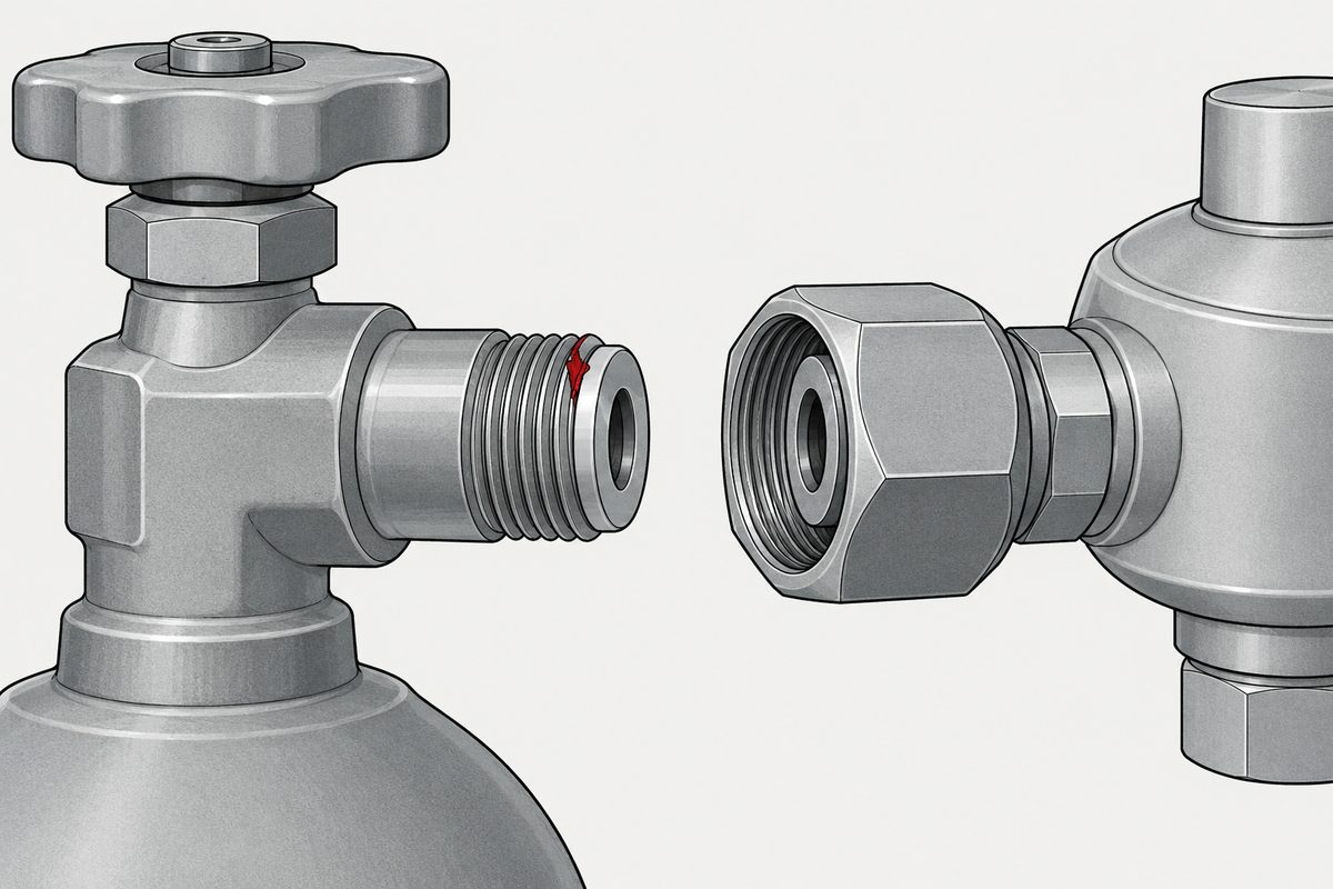
ISO 5145 defines forty two non-interchangeable connections, and they nearly all share the same thread: a Whitworth thread with a pitch of 2 mm, in one of three diameters. What actually keys them apart is a pair of recess diameters, A and B, whose sum is constant for each size and which step in 0,7 mm increments. Two adjacent connections differ by seven tenths of a millimetre on each of two bores and by nothing at all on the overall envelope. And the seal is not on the thread. It is on a cone, held there by the union nut.
The document is ISO 5145:2017, Gas cylinders, cylinder valve outlets for gases and gas mixtures, selection and dimensioning, fourth edition, ISO/TC 58/SC 2, twenty seven pages, confirmed as current in 2023. It says in its introduction exactly what it is for: “The main purpose in standardizing valve outlets is to prevent the interconnection of non-compatible gases.”
This page describes a standard. It is not a safety instruction, it does not tell anybody what to do with a cylinder, and it names no product. The person who posted the photograph returned the cylinder, and that is the last we will say about it.
The thread is chosen by how dangerous the gas is
The selection does not start from pressure or from pipe size. It starts from a code. ISO 14456 allocates to any gas or gas mixture in a cylinder a four digit code, FTSC, which categorises it by flammability, toxicity, state of the gas, including whether it is compressed and at what pressure rating, or liquefied, and corrosiveness. That code puts the gas into one of fifteen compatible gas groups, and each group gets a valve outlet.
Look at the list of normative references and the point becomes hard to miss. Three separate International Standards exist whose titles end in the same clause:
- ISO 10156, determination of fire potential and oxidizing ability for the selection of cylinder valve outlets
- ISO 10298, determination of toxicity for the selection of cylinder valve outlets
- ISO 13338, determination of tissue corrosiveness for the selection of cylinder valve outlets
There is a standard for measuring how corrosive a gas is to tissue, and its stated purpose is choosing a thread. That is a fair summary of the whole system.
The standard is careful about what the code is not. A note states that the only purpose of the numerical code is to group compatible gases together so that the right outlet can be selected, and that it is not intended as an identification code. It is a sorting key, not a label. Labelling and colour coding are separate safeguards, and the scope says this document does not affect them.
Five of the fifteen groups hold exactly one gas each, with mixtures and other gases excluded: group 2 carbon dioxide, group 5 air, group 10 oxygen, group 11 nitrous oxide, group 14 acetylene. Group 15 is reserved for specific gas mixtures.
The step index, and the constant sum
The mechanism is called the step index principle. The valve outlet has a double recess, and the connector has a spigot of two different diameters designed to fit it. The clever part is in one sentence: “The lengths of the recesses and spigots are the same for each connection but the diameters vary depending on the group of gases.”
Table 1 lays out the diameters, and the arithmetic in the next paragraph is ours.
| Nominal diameter | A + B | A runs | Combinations |
|---|---|---|---|
| 24 mm | 28 | 11,2 to 14 | 5 right hand, 5 left hand |
| 27 mm | 32 | 11,8 to 16 | 7 right hand, 7 left hand |
| 30 mm | 36 | 12,4 to 18 | 9 right hand, 9 left hand |
Within each size, A goes up in steps of 0,7 mm and B comes down in steps of 0,7 mm, so their sum never changes. On the 24 mm size the pairs are 11,2 with 16,8, then 11,9 with 16,1, then 12,6 with 15,4, then 13,3 with 14,7, and finally 14 with 14, which is the symmetric one. The largest size does the same thing nine times.
That is the whole security of the system. A spigot built for one group has a small diameter 0,7 mm off and a large diameter 0,7 mm off from its neighbour, in opposite directions, so it cannot enter the neighbour’s recess even though both are the same length, the same nominal diameter, and carry the same thread. Twenty one right hand and twenty one left hand combinations make forty two.
There is also a note that reads like the end of an argument: internal double-recess step index connections are not used because of their excessive size. Somebody proposed putting the recess on the other part, and the answer was that it would be too big.
The thread is the same Whitworth form as a pipe thread
Three nominal diameters, 24, 27 and 30 mm, and one thread form for all of them. Table 2 gives the basic dimensions.
| Nominal, major | Pitch diameter | Minor diameter |
|---|---|---|
| 24 | 22,72 | 21,44 |
| 27 | 25,72 | 24,44 |
| 30 | 28,72 | 27,44 |
Our own check, because it connects two parts of this site. The Whitworth thread height is 0,640 327 P, so at a pitch of 2 the pitch diameter should be the major minus 1,280 654 and the minor should be the major minus 2,561 308. That gives 22,719 346 and 21,438 692 for the 24, and the same subtraction lands on the printed value for all three sizes, six for six. It is the identical formula the pipe thread standards use, at a pitch of 2 mm.
The tolerancing is where it gets pointed. Clause 5 says the tolerances shall be chosen from applicable national standards, or from the example given, and then rules something out explicitly: “Bilateral tolerancing systems, such as those in ISO 2768 (all parts), shall not be used.”
The reason is not stated but is easy to see. A bilateral tolerance lets a dimension go either way from nominal, and in a system whose entire safety rests on parts not fitting, a dimension that can wander in both directions is a dimension that can wander into the next connection. Table 1 marks the bores H10 and the spigots d10, both unilateral. Table 2’s deviations are all unilateral too, the union nut’s pitch diameter running from zero upward and the valve’s from below nominal downward. They are printed as bare numbers with no unit repeated in that table, and we report them as printed rather than deciding for it.
Where the seal is
The poster who found the dent noticed it was near the sealing face. The standard says what that face is.
“Leak tightness is achieved by sealing the end of the connector bearing on the conical part of the valve outlet connection. This seal is maintained by the union nut.”
A connection has three parts: the valve outlet, the connector, and the union nut, which the standard defines as the means by which the connector is secured and by which the seal is ensured. The thread pulls; the cone seals. That is the same division of labour that the parallel pipe thread standard sets out for fittings, and it is the reason a scar near the cone is a different problem from a scar on the thread.
Other sealing methods are allowed, but with a condition attached that tells you what the document actually cares about: provided the non-interchangeability between connector types is maintained. You may change how it seals. You may not change what it will mate with.
Every outlet and connection is also marked. Clause 6 requires the number of the corresponding outlet, and Table 3 assigns one to each combination, with the left hand and right hand versions of the same diameter pair getting different numbers. On the 24 mm size, the 11,2 and 16,8 pair is number 1 right hand and number 6 left hand; the symmetric 14 and 14 pair is 5 and 10.
Nine connections nobody has used yet
Clause 7 opens by stating that thirty three of the forty two available connections are allocated. Our own subtraction: nine are spare. The introduction explains why they exist. The provisions of the document “can be called for in the future in cases where a new gas or gas mixture is developed industrially”.
A committee in the late 1970s built a keying system with nine empty slots in it, on the assumption that chemistry was not finished. That is unusually good planning to find in a dimensional table.
The allocation itself, which gas group gets which number, is in Tables 4 and 5 and the annexes, and those are outside the free preview. This page does not say which connection belongs to which gas, and nothing here should be used to identify one.
The sentence the standard did not have to include
The introduction ends with an admission that is rare in this kind of document, and it reframes everything above it.
“In view of the fact that no country seemed ready to give up their national standards and to adopt an International Standard specifying the dimensions of gas cylinder valve outlets, it was agreed that this document need not be complied with where a national standard predates it.”
And then: “This document thus represents a basis for international agreement in the more or less remote future.”
So the international system designed specifically so that the wrong gas cannot be connected is, by its own text, optional wherever a national system got there first. The document is explicit that this is why the caution matters: because of the multiplicity of connections in use and the existence of many national standards, the concern about compatibility cannot be overstated.
It also explains the design brief. By the end of the 1970s the committee had concluded that the only workable long-term solution was to create a system of valve outlets that would not be interchangeable with the existing systems, on four criteria: safety, simplicity, compactness and tightness. Not compatible with what was already out there. Deliberately, provably not.
What to take from it
- The thread is not the identity of the connection. Three nominal diameters carry forty two different connections, and the thread form is the same Whitworth pitch 2 throughout
- The identity is two diameters that sum to a constant. 28, 32 or 36 depending on size, stepped 0,7 mm at a time, which is our own reading of Table 1
- The seal is on the cone. The union nut secures the connector and maintains the seal; the standard says so in one sentence
- The connections are numbered. Clause 6 requires the outlet and the connection to be marked with the number, and left hand and right hand versions of the same pair have different numbers
- The gas decides, and four other standards decide the gas. Flammability, toxicity, state and corrosiveness, each with its own International Standard whose title says it is for selecting a valve outlet
- An international standard here does not mean a universal one. The document itself says it need not be complied with where a national standard predates it
This page covers step 2, the thread. The whole order is substrate, thread, head, drive, finish, documentation, and why doing it out of order is rework rather than a tweak is in specifying a screw.
Common questions
What decides which thread a gas cylinder valve outlet has?
The gas. ISO 14456 allocates a four digit code, FTSC, describing flammability, toxicity, state of the gas and corrosiveness, and that code assigns the gas to one of fifteen compatible groups. Each group is allocated a valve outlet connection. ISO 5145 states that the main purpose in standardizing valve outlets is to prevent the interconnection of non-compatible gases.
How many cylinder valve outlet connections does ISO 5145 define?
Forty two non-interchangeable connections, twenty one right hand and twenty one left hand, built on three nominal diameters of 24, 27 and 30 mm. Clause 7 states that thirty three of the forty two are allocated, which by our own subtraction leaves nine spare for gases not yet developed industrially.
What makes the connections non-interchangeable if they share a thread?
A pair of recess diameters. The valve outlet has a double recess and the connector has a spigot of two different diameters, and the standard states that the lengths are the same for each connection while the diameters vary by gas group. By our own reading of Table 1, the two diameters always sum to a constant for each size, 28, 32 or 36, and step in increments of 0,7 mm.
What thread is used on a cylinder valve outlet under ISO 5145?
A Whitworth thread with a pitch of 2 mm, in nominal diameters of 24, 27 and 30 mm. The pitch diameters printed are 22,72, 25,72 and 28,72 and the minor diameters 21,44, 24,44 and 27,44. By our own arithmetic those follow the Whitworth height of 0,640 327 P, the same formula the ISO pipe thread standards use.
Where does a cylinder valve connection seal?
On a cone, not on the thread. ISO 5145 states that leak tightness is achieved by sealing the end of the connector bearing on the conical part of the valve outlet connection, and that this seal is maintained by the union nut. Other sealing methods are allowed provided the non-interchangeability between connector types is maintained.
Why does ISO 5145 forbid bilateral tolerances?
It states plainly that bilateral tolerancing systems, such as those in ISO 2768, shall not be used, without giving a reason. Table 1 designates the bores H10 and the spigots d10, and the deviations in Table 2 are all unilateral. In a system whose safety rests on parts not fitting, a dimension free to move in both directions is a dimension free to move towards the next connection.
Are the connections marked?
Yes. Clause 6 requires the outlets and the connections to be marked with the number of the corresponding outlet, and Table 3 assigns a number to each combination of diameters, with separate numbers for the left hand and right hand versions of the same pair.
Is ISO 5145 mandatory?
By its own text, not where a national standard came first. The introduction states that in view of the fact that no country seemed ready to give up their national standards, it was agreed that the document need not be complied with where a national standard predates it, and describes itself as a basis for international agreement in the more or less remote future.
Which gases get a connection all to themselves?
Five of the fifteen groups hold a single named gas each, with mixtures and other gases excluded: group 2 carbon dioxide, group 5 air, group 10 oxygen, group 11 nitrous oxide and group 14 acetylene. Group 15 is reserved for specific gas mixtures.
References
- ISO 5145:2017, Gas cylinders, cylinder valve outlets for gases and gas mixtures, selection and dimensioning. Introduction, clauses 1 to 6, Tables 1 to 3, Figures 1 and 2
- r/metalworking, where the photograph of a dented cylinder valve thread was posted this month
The text used here is the publicly available iTeh preview of ISO 5145:2017, which runs to page 6 of a 27 page document. It contains the introduction, clauses 1 to 6 in full, Tables 1 to 3 and Figures 1 and 2. Clause 7 beyond its opening sentence, Tables 4 and 5, and Annexes A, B and C are not in the preview, so this page does not say which connection is allocated to which gas group and nothing here should be used to identify a connection. The standard is the fourth edition, twenty seven pages, ISO/TC 58/SC 2, stage 90.93, last reviewed and confirmed in 2023. The following is our own arithmetic, not a statement by the standard: that A and B step in 0,7 mm increments while their sum stays constant, the Whitworth check of the pitch and minor diameters against 0,640 327 P, and the count of nine unallocated connections. Every numeral was checked against a rendered image of the printed page. The tolerance deviations in Table 2 are printed without a unit being repeated in that table, and we report them as printed rather than deciding what unit is intended. Nothing is quoted from ISO 14456, ISO 10156, ISO 10298, ISO 13338, ISO 286 or ISO 2768 beyond their titles and the sentences of ISO 5145 that name them; none of those were read. This page describes a standard. It is not a safety instruction, it gives no guidance on handling compressed gas or cylinders, and it identifies no product, gas supplier or cylinder. The forum post is cited as the source of the question; we read the post and not its replies, so nothing from the replies appears here.
Enquiries
If a threaded gas connection is part of an assembly you are specifying, identify it by the outlet number the standard requires to be marked on it, not by the thread size. Three nominal thread diameters carry forty two different connections, and the thread is the part they have in common.
Request a quotation
Tell us the part and the quantity. We will come back on feasibility, lead time and price.
Or email us directly sales@tigerfasteners.com