 TIGERFASTENERS
A Phillips Driver Tip Has Its Own Table, and Every Size Gets the Same Five Hundredths
An engineering forum spent a hundred comments this month on why a cheap cross-head driver strips screws and an expensive one does not. Almost every answer said tolerances, and not one of them opened the table. The recess has a standard, which people quote often enough. The tip that goes into it has a separate standard, which almost nobody reads, and it turns out to say something odd: the permitted band on the tip width is the same five hundredths of a millimetre whether the blade is three millimetres across or ten.
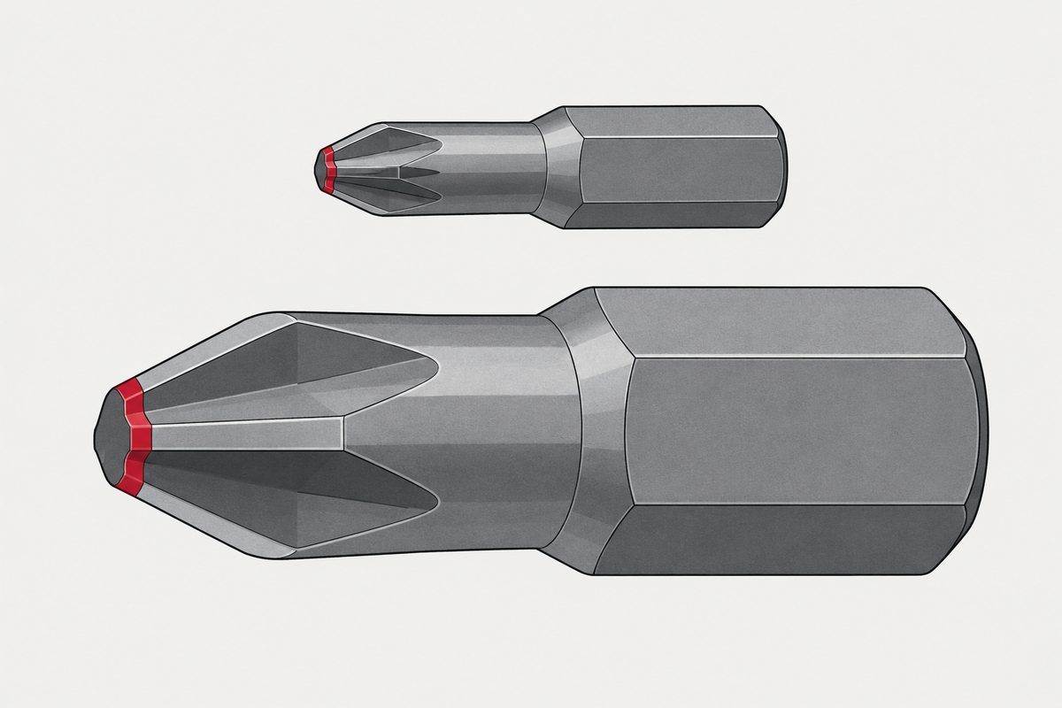
In ISO 8764-1, Table 1, the width across the wings of a form PH tip is 0,61 to 0,56 mm for a number 0 and 3,60 to 3,55 mm for a number 4. Different sizes, same band: 0,05 mm. Five hundredths, or five of what a Taiwanese machine shop calls a tiao. Every size in the table gets it. Meanwhile the gap between a number 1 at its largest and a number 2 at its smallest is 0,48 mm, which is our own subtraction and works out at about ten of those bands.
The document is ISO 8764-1:2004, Assembly tools for screws and nuts, screwdrivers for cross-recessed head screws, part 1: driver tips, third edition, ISO/TC 29/SC 10, confirmed as current in a 2024 review. It specifies two forms: form PH for form H recesses and form PZ for form Z recesses. The recesses themselves are somebody else’s job, ISO 4757, and the blade length and marking are part 2. This part covers the working end alone, for hand drivers and for machine-operated bits together.
The table
Five sizes, numbered 0 to 4, each given as a pair of limits. Nothing smaller than a number 0 appears.
| Tip | Nominal blade dia. | b, across wings | g | l min | α | β |
|---|---|---|---|---|---|---|
| 0 | 3 mm | 0,61 / 0,56 | 0,84 / 0,79 | 2,78 | see figure | 7°00′ / 6°30′ |
| 1 | 4,5 mm | 1,03 / 0,98 | 1,30 / 1,25 | 2,78 | 138°30′ / 138°00′ | 7°00′ / 6°30′ |
| 2 | 6 mm | 1,56 / 1,51 | 2,31 / 2,26 | 4,37 | 140°30′ / 140°00′ | 5°45′ / 5°15′ |
| 3 | 8 mm | 2,52 / 2,47 | 3,84 / 3,79 | 6,74 | 146°30′ / 146°00′ | 5°45′ / 5°15′ |
| 4 | 10 mm | 3,60 / 3,55 | 5,11 / 5,06 | 8,34 | 153°30′ / 153°00′ | 7°00′ / 6°30′ |
Both length columns behave the way you would expect. The nominal blade diameter runs 3, 4,5, 6, 8, 10, and the minimum straight length runs 2,78 up to 8,34. The tolerance does not follow them. On b it is 0,05 in every row. On g it is 0,05 in every row. On the two angles it is 0°30′ in every row.
Two columns break the pattern, and they are worth naming because they are the only places the committee spent tolerance unevenly. e, the width across the flute openings, is 0,38 to 0,29 on a number 0, a band of 0,09, and 0,05 everywhere else. f, the small central width, is 0,05 on tips 0, 1 and 2 and 0,08 on tips 3 and 4. The big tips are allowed a looser middle.
The flute angle is not monotonic either. β is 7°00′ to 6°30′ on tips 0, 1 and 4, and 5°45′ to 5°15′ on tips 2 and 3. The two sizes in the middle, which are the two that most people own, have a shallower flute than the sizes on either side of them.
Whether a number 2 can drift into a number 1
This is the question the forum was actually asking, in the form of an observation: one brand’s number 2 would turn a number 1 screw badly, another brand’s number 2 would not go in at all. The poster wondered whether the loose one was deliberate.
Take the subtraction first, and note that the arithmetic below is ours, not the standard’s. On b, the smallest permitted number 2 is 1,51 and the largest permitted number 1 is 1,03. The gap is 0,48 mm. The band inside which a number 2 has to sit is 0,05. So a tip would have to be nine or ten whole tolerance bands undersize before its width across the wings reached the top of the size below. Tool wear does not do that. Whatever is happening when a number 2 turns a number 1, it is not a number 2 that has drifted.
The reason it goes in anyway is in the figure rather than the table. A PH tip is a cone, drawn with a half angle of 26°30′, tolerance 0 to minus 0°30′, with four flutes equally spaced at 90°. Every cone is narrow near its point. A number 2 will always enter a number 1 recess to some depth, because its nose is thinner than the recess mouth. What decides whether it does any work is how deep it sits before the flanks touch.
And that, it turns out, is the thing the standard actually controls.
The gauge measures depth, and says so
Clause 5 does not ask anybody to measure a tip with a micrometer. It defines an inspection gauge, and a tip conforms
“when they fit properly into the gauge and when the edges of the tips at which the two cones of 53° and 142° meet and lie within step c of the gauge.”
53° is twice the 26°30′ half angle from the figure. The edge where the two cones meet is the shoulder of the tip, and the question the gauge asks is where that shoulder lands along the axis. A note under the PZ gauge table puts it plainly: “The inspection gauge can only be used for checking the penetration depth of tool profiles. Through this the fitting precision of the tool profiles in the referring screw heads is guaranteed.”
Now look at what step c is. In Table 3 it is a single merged cell covering all five sizes: 0,254 mm, plus or minus 0,025. A number 0 gauge and a number 4 gauge use the same window. Whatever else scales with size, the depth window does not.
That is a quarter of a millimetre, and it is the number the forum was groping for. A tip that sits a quarter of a millimetre too shallow is out of gauge. A tip that sits right engages the flanks it was drawn to engage. Nobody in that thread measured depth, because depth is not a thing you can feel except as the thing they all described, which is a driver that either bites or does not.
The gauge is built at the worst end of the tip
There is an informative annex called Explanation of choice of gauge dimensions for form PH tips, and it is not in the free preview, so we cannot tell you what it says. What we can do is put Table 1 and Table 3 side by side, which is our own comparison rather than the standard’s.
| Gauge dimension | Its tolerance | Equals, in Table 1 |
|---|---|---|
| m | 0 / −0,02 | The minimum of e, all five sizes (0,29 / 0,49 / 1,08 / 2,07 / 2,71) |
| α | 0 / −0°15′ | The minimum of α (138° / 140° / 146° / 153°) |
| β | +0°15′ / 0 | The maximum of β (7° / 7° / 5°45′ / 5°45′ / 7°) |
| b | min. | The nominal blade diameter (3 / 4,5 / 6 / 8 / 10) |
Every one of those matches exactly, and each one is taken from the end of the tip tolerance where the gauge is hardest to pass, then given a further quarter degree or two hundredths in the same direction. The gauge is not a copy of the nominal tip. It is a copy of the worst tip the table still allows, so that anything which goes in is inside the band by construction.
The number 0 row has a dash where α should be. That matches Table 1, where the number 0 tip has no α value either and the cell reads see Figure 1. In the figure, the number 0 tip is drawn with only the 92° +0°30′ / 0 flute angle that the other sizes carry alongside α, and a small radius detail of R0,28 to R0,21. The smallest tip is a different shape, not a scaled one.
The gauge is an inch drawing wearing millimetres
The rest of Table 3 is where it gets interesting, and again the arithmetic here is ours. Start with step c, the depth window that is the same at every size: 0,254 mm is 0,010 inch exactly. Its tolerance of ±0,025 mm is a thousandth of an inch to within a rounding. A metric standard would not choose 0,254. An inch drawing would choose ten thou without thinking about it.
Then dimension a, quoted to three decimal places with a tolerance of ±0,005 mm, which is a strange thing to ask for in millimetres.
| Tip | a, as printed | In inches | Converted back |
|---|---|---|---|
| 0 | 0,419 | 0,0165 | 0,4191 |
| 1 | 0,648 | 0,0255 | 0,6477 |
| 2 | 1,156 | 0,0455 | 1,1557 |
| 3 | 1,918 | 0,0755 | 1,9177 |
| 4 | 2,553 | 0,1005 | 2,5527 |
All five land on a round inch value plus half a thousandth. Sixteen and a half thou, twenty five and a half, forty five and a half, seventy five and a half, a hundred and a half. That is not a coincidence you get from converting metric numbers.
The e column tells the same story in fractions. 2,38 is three thirty-seconds of an inch, 2,38125, rounded. 3,97 is five thirty-seconds, 3,96875. 7,94 is five sixteenths, 7,9375. The remaining entry is 6,34, and a quarter inch is 6,35. We report that as printed. We have no explanation for the hundredth, we are not calling it an error, and the annex that might have explained where these came from is behind the paywall.
Two columns resist the conversion. f produces nothing round in inches, which fits a value derived trigonometrically from the cone angles rather than drawn. And m we already know comes straight from the metric tip table. So the gauge’s own geometry looks inherited from an inch drawing, and the parts of it that are tied to the tip come from the millimetre side. Which is roughly the history of the whole recess.
PH and PZ share a cone and disagree about which way it may lean
Both figures draw the same nominal half angle of 26°30′, and both draw the same ≤19° lead-in on the flutes. The tolerance is where they part.
| Cone half angle | Band on b | |
|---|---|---|
| Form PH | 26°30′, 0 to −0°30′ | 0,05 at all five sizes |
| Form PZ | 26°30′, +0°30′ to 0 | 0,08, 0,08, 0,08, 0,10, 0,10 |

Same nominal, opposite directions. A conforming PH tip is 26°00′ to 26°30′. A conforming PZ tip is 26°30′ to 27°00′. The two permitted ranges touch at one value and do not overlap anywhere else.
And the width band runs the other way from the folk wisdom. PZ, the form with the extra ribs at 46° +0°15′ / 0 and the reputation for gripping better, is given a wider tolerance on b than PH at every size: eight hundredths on the small three and a tenth of a millimetre on the big two, against five hundredths throughout for PH. Whatever PZ buys you, the tip table does not buy it with a tighter width.
Three sentences that matter more than the tables
Clause 3 ends with a line that belongs to the coating half of this site: “When a plated finish is used, the dimensions shall be met after plating.” The number in Table 1 is a finished dimension. A tip plated after grinding has to come out the far side of the plating line still inside five hundredths, which is a real constraint on how thick that plating can be. The same sentence is in the 1999 edition, word for word.
Clause 4.2 sets hardness by service rather than by size: 54 HRC minimum for hand-operated screwdrivers, 58 HRC minimum for machine-operated ones, and the hardened zone has to run three times the nominal blade diameter back from the driving end. For a number 2 that is 18 mm. The rest of the tool is hardened and tempered to a minimum of 50 HRC. Readings are to be taken on ground flats, parallel with the axis, large enough to read accurately.
A bit for a power tool is therefore held four points harder than the same profile on a handle, and the standard gives the reason nowhere. It simply splits the requirement by how the tool will be used.
What changed between 1999 and 2004
We pulled the previous edition to check, because a table that has not moved is worth knowing about. The 2004 foreword lists the revision in full: a designation has been added; in the English version the term point becomes tip and type becomes form; in the French version type becomes forme. That is the whole list.
Comparing the two previews confirms it. Table 1 and Table 2 are identical cell for cell. The 26°30′ figures are identical. The plating sentence is identical. What a form PH number 2 tip is allowed to measure has not changed since at least 1999, and the 1999 foreword says its own revision touched information on points and gauges for type PZ, with an introduction explaining that the PZ drawings were redone to eliminate different interpretations. So the PH side may well be older still, though we have not read the 1992 edition and are not claiming it.
One methodological note, because it nearly caught us. Text extracted from these PDFs attaches merged table cells to different rows in the two editions, which makes the PZ angle columns look as though they moved between 1999 and 2004. They did not. Rendering the printed page as an image and reading the cell borders shows the same merges in both. We now check every numeral against a page image before writing it down, and this is the fourth time that habit has killed a finding that was not there.
What the standard does not say
Within the seven pages that are public, the word cam does not appear. Neither does any reference to a torque at which a tip is meant to leave the recess. Clause 6 is a torque test and we have not read it, but the scope calls it a test method, which is a different thing from a design intent. That is consistent with what the two original patents turned out to say, which is also nothing.
The standard also says nothing about any national cross-recess system, and we have not read one, so this page does not compare them. Half the forum thread was people explaining to each other that the driver in their hand might belong to a different system than the screw. That is a real problem and it deserves its own primary source, which we do not have yet.
And there are no sizes below 0. If a bit is sold as a triple zero, it is not in this table.
How to use it
- Ask for the gauge, not the dimension. Conformance in this standard is defined by fitting the inspection gauge with the cone shoulder inside step c, and step c is 0,254 mm at every size
- Expect a size step to be about ten tolerance bands. On b, a number 1 tops out at 1,03 and a number 2 starts at 1,51, against a band of 0,05. A tip that works in the size below is not a tip that drifted
- Say hand or machine when you specify hardness. The standard sets 54 HRC and 58 HRC for the two cases, over three times the blade diameter
- Remember the dimensions apply after plating. Clause 3 says so in one line, and it constrains the coating as much as the grinding
- Do not assume PZ means tighter. The band on b is 0,05 for PH at every size and 0,08 to 0,10 for PZ
The forum answer that got the most agreement was that you get what you pay for, which is true and does not tell you what to write on a drawing. The table tells you what to write on a drawing. It has been sitting in a twenty two page document since before most of the people arguing about it bought their first driver.
The hexagon socket drive has the same arrangement, a tool standard and a screw standard with tolerances running in opposite directions, and there the two tables can be laid side by side because both are dimensional: a hex key never reaches the corners of the socket.
This page covers step 4, the drive. The whole order is substrate, thread, head, drive, finish, documentation, and why doing it out of order is rework rather than a tweak is in specifying a screw.
Common questions
Which standard sets the dimensions of a Phillips driver tip?
ISO 8764-1, Assembly tools for screws and nuts, screwdrivers for cross-recessed head screws, part 1: driver tips. The current version is the third edition of 2004, prepared by ISO/TC 29/SC 10 and confirmed as current in a 2024 review. It covers two forms, PH for form H recesses and PZ for form Z recesses. The recesses themselves are in ISO 4757 and the blade lengths and marking are in part 2.
How much tolerance does a driver tip get?
On the width across the wings, dimension b, the band is 0,05 mm for every one of the five sizes, from the number 0 with a 3 mm nominal blade to the number 4 with a 10 mm blade. Dimension g has the same 0,05 band throughout, and both angles are held to 30 minutes of arc. The exceptions are e on the number 0, which gets 0,09, and f on the numbers 3 and 4, which gets 0,08.
Can a number 2 driver tip be small enough to turn a number 1 screw?
Not by drifting inside its own tolerance. The smallest permitted number 2 measures 1,51 mm across the wings and the largest permitted number 1 measures 1,03 mm, a gap of 0,48 mm against a tolerance band of 0,05 mm, so nine or ten whole bands would have to be lost. A tip does enter a smaller recess to some depth in any case, because the tip is a cone with a 26 degree 30 minute half angle and its nose is narrower than the recess mouth. What the standard controls is how deep it sits.
What does the inspection gauge actually check?
Penetration depth. A note in the standard states that the inspection gauge can only be used for checking the penetration depth of tool profiles, and that fitting precision in the matching screw heads is guaranteed through that. A tip conforms when it fits the gauge and the shoulder where the two cones of 53 and 142 degrees meet lies within step c, which is 0,254 mm plus or minus 0,025 at all five sizes.
Do PH and PZ tips have the same cone angle?
The same nominal angle and opposite tolerances. Both figures draw a half angle of 26 degrees 30 minutes. The PH figure allows 0 to minus 30 minutes, so 26 degrees 00 minutes to 26 degrees 30 minutes. The PZ figure allows plus 30 minutes to 0, so 26 degrees 30 minutes to 27 degrees 00 minutes. The two ranges touch at one value and do not overlap.
Are PZ tips held to a tighter tolerance than PH?
Not on the width across the wings. ISO 8764-1 gives PH a band of 0,05 mm at all five sizes, and gives PZ 0,08 mm on the three small sizes and 0,10 mm on the two large ones.
Does a driver tip dimension apply before or after plating?
After. Clause 3 states that when a plated finish is used, the dimensions shall be met after plating. The same sentence appears word for word in the 1999 edition.
How hard does the standard require the tip to be?
A minimum of 54 HRC for hand-operated screwdrivers and 58 HRC for machine-operated ones, over a minimum length of three times the nominal blade diameter measured from the driving end. The remainder of the tool is hardened and tempered to a minimum of 50 HRC, and all hardness readings are to be taken on ground flats parallel with the axis.
Does the standard say the tip is designed to cam out?
The word cam does not appear anywhere in the seven pages that are publicly readable, and there is no reference to a torque at which the tip is meant to leave the recess. Clause 6 is a torque test method, which is not the same as a design intent, and it is behind the paywall.
References
- ISO 8764-1:2004, Assembly tools for screws and nuts, screwdrivers for cross-recessed head screws, part 1: driver tips. Clauses 1 to 5, Figures 1 to 4, Tables 1 to 4
- ISO 8764-1:1999, the withdrawn second edition, used here only to compare the tables
- r/AskEngineers, the thread this started in, a hundred comments on why one driver bites and another does not
- Phillips driver size chart — the recess number on the screw side: M3 is No. 1
The text used here is the publicly available iTeh preview of ISO 8764-1:2004, which runs to page 7 of a 22 page document. It contains clauses 1 to 5 in full, Figures 1 to 4 and Tables 1 to 4. Clause 6, the torque test, clause 7, the designation, and the two informative annexes are not in the preview, and nothing on this page describes them. Annex A is titled Explanation of choice of gauge dimensions for form PH tips and appears in the contents list; its content is not public and we have not seen it. The 1999 edition was read from the corresponding preview and used only to compare Tables 1 and 2 and the figures. The following are our own arithmetic on the printed tables, not statements by the standard: the size-to-size gaps on dimension b, the division of that gap by the tolerance band, the correspondence between the gauge dimensions m, alpha, beta and b and the tip limits in Table 1, and every inch conversion. The 6,34 entry in the gauge e column sits 0,01 mm from a quarter of an inch and we report it as printed without explaining or correcting it. Every numeral on this page was checked against a rendered image of the printed page, because text extraction attached the merged angle cells of Table 2 to different rows in the two editions, which would have read as a change between them; the page images show identical merges. No dimension from ISO 4757 is quoted here, and nothing from ISO 8764-2. No national cross-recess standard is quoted, because we have not read one. No tool brand is named. The forum thread is cited as the source of the question only.
Enquiries
If a driver tip or bit matters to your assembly, cite the form and the size the way the standard does, PH or PZ with a number from 0 to 4, and ask whether conformance was established with the inspection gauge. Ask also whether the dimensions were verified after plating, since that is where the standard puts the check.
Request a quotation
Tell us the part and the quantity. We will come back on feasibility, lead time and price.
Or email us directly sales@tigerfasteners.com