 TIGERFASTENERS
On a Bolt Circle the Angles Between the Holes Are Implied and the Grouping Is Not
Draw four holes equally spaced on a circle and you have told the reader the angle between them without writing a number. The standard that governs this says so explicitly: the ninety degrees is an implicit theoretically exact dimension. What the same picture does not tell the reader is whether those four holes are one thing or four things. That has to be written down, and under the previous edition of the same standard it did not.
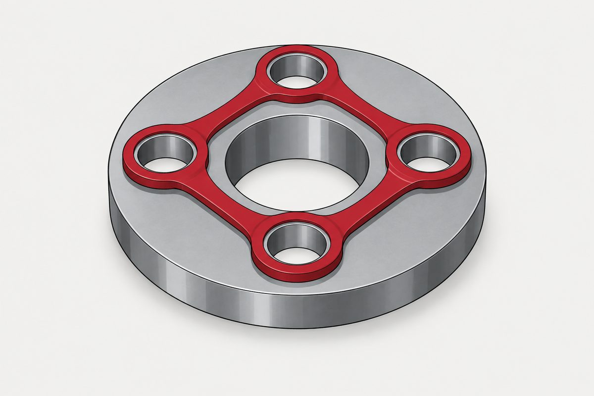
One of the implicit exact dimensions listed is “equally disposed angle, 360°/n, where n is the number of features in a pattern shown equally disposed on a circle”. Two clauses earlier, the same document says that by default a specification applying to more than one feature applies to those features independently, and that this “corresponds to the meaning of the modifier SZ”, separate zones.
This page gives no advice on tolerancing, drawing indication or measurement, and makes no judgement about any particular drawing. It did not come from a forum question; it comes from the method the last article produced, which is to list the standards this site has already cited and pick the one with almost no coverage. The browser tooling we normally use remains unavailable.
Which document, and how much of it we could read
The standard is ISO 5458, on pattern and combined geometrical specification, third edition dated May 2018, prepared by ISO/TC 213 and replacing an edition from 1998. Twenty years separate them, by our arithmetic. This is the second document from that committee this site has used, after the one that writes down the assumptions all the others are read under.
The free preview covers the front matter and the body as far as subclause 5.4.3, out of a document running to forty four pages. In particular we did not read Annex A, which is titled former practice and important changes, or Annex B, on the differences from the 1998 edition. Everything this page says about the older edition comes from a note in the body, not from those annexes. We also did not read the later rules, the examples, or any of the referenced standards, and we did not check whether the document is current.
There is one more thing we did not do, and the standard asked for it. A boxed notice at the head of the document says its illustrations are “not fully dimensioned and toleranced”, are “not a representation of a complete workpiece” and are “not of a quality that is required for use in industry”, and concludes that they are “not suitable for projection for teaching purposes”. A standard that opens by telling you not to teach from its own pictures is worth taking at its word, so no figure is described here.
What the picture says without words
The rule on constraints lists the exact dimensions a drawing carries implicitly, without anyone writing a number. There are four, and each ends with the same condition, that there is no explicit indication to the contrary.
- Zero millimetres, where drawing lines appear straight or aligned
- Zero, ninety, one hundred and eighty, or two hundred and seventy degrees, where lines appear aligned or perpendicular
- An equally disposed angle of 360° divided by n, where n features are shown equally disposed on a circle
- Angular alignment between coaxial patterns
The third of those is the bolt circle. Six holes drawn evenly around a flange carry sixty degrees between them as an exact value, and nobody has to write it. The picture is the specification.
The standard then adds a note suggesting you write it anyway: to help readability, it says, it can be useful to indicate explicitly the dimensions that could be considered implicit. That is a document recommending you state what it has just told you that you do not have to state. Anyone who has had a drawing come back with a question about the spacing will recognise why.
There is a related rule for the modern case. If the values come out of the model rather than the sheet, that has to be indicated near the title block. The implicit values are implicit in the picture; where the picture is not the source, you say so.
What the picture does not say
The angles are free. The grouping is not.
The general clause states the default plainly. A geometrical specification that applies to more than one single feature applies to those features independently, and the tolerance zones are to be considered independently whether they come from one tolerance indicator or several. That is the meaning of the modifier for separate zones. Four holes given one position tolerance are four separate requirements, not one pattern.
The standard attributes that default to the independency principle in the fundamentals standard, citing a particular subclause of it. We should be careful here: that subclause is one of the ones our earlier reading could not see, because the preview stopped short of it. So what we have is this standard stating what that principle requires, not the principle in its own words.
And when it matters, the standard makes you choose. Where a position specification applies to several features and the tolerance zones have at least one unlocked degree of freedom, one of the three modifiers shall always be indicated: separate zones, combined zone, or combined zone rotational only. There is no silent option.
One combination is ruled out on the spot. Using the separate zones modifier on a position specification with no datum section “makes the specification meaningless”. The symbols are all legal; the sentence they form says nothing.
It used to be the other way round
A note under that rule explains why it exists. The 1998 edition, it says, was in conflict with the independency principle, because a pattern specification without the combined zone modifier implied that the tolerance zones of the repeated specifications were related to each other by internal constraints, and therefore dependent. The new rule removes the conflict.
Read that slowly. Under the old edition the holes were a group unless you said otherwise. Under the current one they are separate unless you say otherwise. The default did not move a little; it inverted.
We are not saying anything about any particular drawing, old or new, and this page is not the place to work out what any given sheet means. What is worth carrying is the general shape: a drawing does not carry its own edition, and the same marks can be a different requirement depending on which rules a reader brings.
The list of changes in the foreword contains one more line in the same spirit: “unstated rules in ISO 5458:1998 removed”. You can only remove an unstated rule if it was doing something. The last article found the fundamentals standard saying its own principles had been implied but not formulated explicitly until 2011; here is a general standard doing the same housekeeping in 2018, on rules nobody had written down.
When the difference is real and when it is bookkeeping
The standard is careful about when the choice changes the part and when it only changes the paperwork.
Where the specifications refer to a datum system that locks all degrees of freedom of the tolerance zones, there is no functional difference between n identical individual specifications and one pattern specification with n members. The difference is in how many characteristics you have named: one pattern characteristic against n individual ones.
Where the datum system does not lock all degrees of freedom, or where there is no datum system at all, there is a functional difference. That is the case the modifiers exist for, and it is the case a bolt circle on a plain flange face tends to be.
The scope also draws two lines around itself: it does not cover pattern specifications when the least or maximum material requirement is applied, and it does not cover establishing a common datum from pattern features. Both are sent elsewhere. We did not read either of those documents.
What this settles and what it does not
- The angle between features equally disposed on a circle is an implicit exact dimension of 360 degrees divided by n, absent explicit indication to the contrary
- Three other implicit exact dimensions are listed: zero millimetres, the right angles, and angular alignment between coaxial patterns
- A note suggests indicating implicit dimensions explicitly anyway, to help readability
- Where the values come from the model rather than the drawing, that must be indicated near the title block
- By default a specification on more than one feature applies to them independently, which is the meaning of the separate zones modifier
- For a position specification with an unlocked degree of freedom, one of separate zones, combined zone or combined zone rotational only shall always be indicated
- Separate zones on a position specification with no datum section is called meaningless by the standard
- The 1998 edition implied the grouping where the current one does not, which the standard describes as a conflict with the independency principle
- The foreword records that unstated rules in the 1998 edition were removed
- The choice has no functional difference when the datum system locks all degrees of freedom, and a functional difference when it does not or when there is no datum system
- The statement of the independency principle here is this standard describing another one, not that other standard in its own words
- We did not read the annexes on former practice and on differences from the 1998 edition, nor the later rules, the examples, or any referenced standard, and we did not check whether the document is current
- No advice on tolerancing or drawing indication is given, and no judgement is made about any particular drawing
The transferable habit is to ask which parts of a drawing are carried by the picture and which have to be carried by a mark. Here the answer is unusually clean and unusually easy to get backwards: the geometry of the arrangement is free, and the question of whether the arrangement is one thing is not. When a default inverts between editions, the marks that were unnecessary become the only thing keeping the meaning.
This page covers step 6, the documentation. The whole order is substrate, thread, head, drive, finish, documentation, and why doing it out of order is rework rather than a tweak is in specifying a screw.
Common questions
Do I have to write the angle between holes on a bolt circle?
The standard lists an equally disposed angle of 360 degrees divided by n as an implicit theoretically exact dimension where n features are shown equally disposed on a circle, absent explicit indication to the contrary. A note adds that indicating implicit dimensions explicitly can be useful for readability.
Are several holes with one position tolerance automatically a pattern?
Not under this edition. It states that by default a specification applying to more than one single feature applies to those features independently, which is the meaning of the separate zones modifier. A pattern has to be created with the combined zone, combined zone rotational only, or simultaneous requirement modifiers.
Was that always the rule?
No. A note in the standard says the 1998 edition was in conflict with the independency principle, because a pattern specification without the combined zone modifier implied that the tolerance zones were related by internal constraints and therefore dependent. The current rule removes that conflict.
Does that mean older drawings are wrong?
This page makes no judgement about any particular drawing. It reports what the two editions of the standard say about the default, and nothing more.
When must a modifier be indicated?
Where a position specification applies to several geometrical features and the tolerance zones have at least one unlocked non redundant degree of freedom, the standard says one of separate zones, combined zone, or combined zone rotational only shall always be indicated in the tolerance section.
Does the choice always change anything physical?
No. Where the specifications refer to a datum system that locks all degrees of freedom of the tolerance zones there is no functional difference, only a difference in how many characteristics are defined. Where the datum system does not lock all degrees of freedom, or there is no datum system, there is a functional difference.
What if the exact values live in the CAD model?
The standard says that if the values are extracted from the model, this shall be indicated near the title block.
Why are no figures described here?
The standard opens with a notice saying its illustrations are not fully dimensioned and toleranced, are not a representation of a complete workpiece, are not of a quality required for use in industry, and are not suitable for projection for teaching purposes. We took that at its word.
Is this standard current?
This page does not say. We did not check, because the catalogue page refuses requests from this site.
References
This is a digital document rather than a scan, so text extraction is reliable on it; every quotation here was still checked word by word against the file. The preview covers the body only as far as subclause 5.4.3 of a forty four page document. We did not read Annex A on former practice and important changes, or Annex B on the differences from the 1998 edition, so everything said here about the older edition comes from a note in the body rather than from those annexes. We also did not read the later rules, the examples, the graphical symbol annex, or any of the referenced standards, and we did not check whether the document is current or superseded, because the catalogue page refuses requests from this site. No figure is described on this page, because the standard opens by stating that its illustrations are not suitable for projection for teaching purposes. The statement of the independency principle quoted here is this standard describing a subclause of the fundamentals standard, not that subclause in its own words; the earlier page on that standard could not read the subclause, and that limit is repeated rather than glossed over. The following is our own arithmetic, not a statement in the standard: that twenty years separate the two editions. This is the second document from this technical committee that the site has used, and the earlier page is linked rather than repeated. This page makes no judgement about any particular drawing, old or new, and gives no advice on tolerancing, drawing indication or measurement. This article did not come from a forum question; it comes from listing the standards this site had already cited and picking one with almost no coverage. No brand is named. The browser tooling this site normally uses remains unavailable.
Enquiries
If a hole pattern on your drawing has to hold its arrangement rather than each hole holding its own position, that is a different requirement and it is worth being explicit about. Tell us which one the part actually needs and we will tell you what we can evidence.
Request a quotation
Tell us the part and the quantity. We will come back on feasibility, lead time and price.
Or email us directly sales@tigerfasteners.com